


536636-UIM-D-1211
6 Johnson Controls Unitary Products
TXV METERING DEVICES
If the model (C) number is of the following format: 4F, 4G, 4H, 4J,
and 4K will have the coil with R410A TXV metering device installed at
the factory.
If the model (C) number is of the 3X model series:
The coil will require an orifice or R410A TXV to be installed in the field.
Refer to installation manual with TXV kit. It is recommended to install a
orifice or TXV kit prior to brazing line sets.
Please refer to Outdoor Unit Tech Guide to verify which metering device
is installed in this coil and that this is a valid system match for the AC or
HP unit installed.
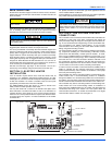
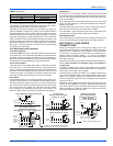
The temperature sensing bulb is attached to the coil suction header
line.
REFRIGERANT LINE CONNECTION
Connect lines as follows:
1. Suction and liquid line connections are made outside the cabinet.
Leave the tubing connection panel attached to the cabinet with the
tubes protruding through it. Coil access panel should be removed
for brazing. The lines are swedged to receive the field line set
tubes.
2. Cut the end of the suction tube using a tube cutter. Place the tube
cutter as close as possible to the end of the tube to allow more
space for the connection and brazing of the suction line.
3. Remove the heat shield from the Customer Packet, soak in water,
and install over coil tubing to prevent overheating of cabinet.
4. Wrap a water soaked rag around the coil connection tubes inside
the cabinet to avoid damaging the TXV bulb.
5. Remove grommets where tubes exit the cabinet to prevent burning
them during brazing.
6. Purge refrigerant lines with dry nitrogen. Follow outdoor unit braz-
ing instructions.
7. Braze the suction and liquid lines.
8. Remove the heat shield.
9. Re-attach the grommets to the lines carefully to prevent air leak-
age.
10. Attach the coil access panel to the cabinet.
Refer to Outdoor unit Installation Manual for evacuation, leak check and
charging instructions.
Lines should be sound isolated by using appropriate hangers or strap-
ping.
All evaporator coil connections are copper-to-copper and should be
brazed with a phosphorous-copper alloy material such as Silfos-5 or
equivalent. DO NOT use soft solder.
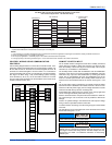
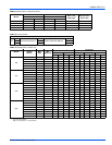
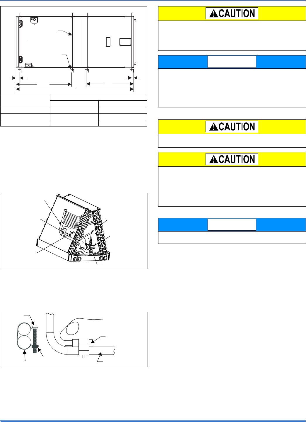
Units
(Nominal Tons)
Dimension
WW XX
24B 20 46
36C 24 52
AV*48D, 60D 28 57
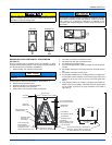
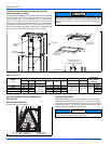
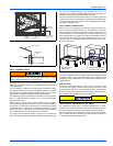
FIGURE 8: Typical Horizontal Installation
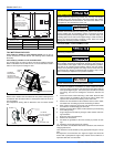
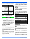
FIGURE 9: TXV
FIGURE 10: Proper Bulb Location
WW
XX
SUSPENSION SUPPORT LOCATIONS FOR HORIZONTALAPPLICATIONS
2
1-1/2
MIN. 1-1/2” x 1-1/2”
Angle Recommended
length 26” minimum with
2” clearance on both
sides ofAir Handler
MIN. 3/8”
THREADED ROD
YY
VAPOR
LINE
THERMAL
EXPANSION
VALVE BULB
(Required insulation
not shown for clarity)
THERMAL
EXPANSION
VALVE
DISTRIBUTOR BODY
LIQUID
LINE
TXV
EQUALIZER
LINE
TXV BULB
(Cover completely
with insulation)
SCREW
CLAMP
NUT
SUCTION LINE
COIL UNDER PRESSURE.
Relieve pressure by depressing schrader core. Coil may have factory
installed TXV or may require orifice or TXV to be added. See outdoor
unit documentation for correct orifice or TXV to be used. Refer to coil
nameplate for TXV identification for this unit.
The coil should be open to the air for no more than 2 minutes to keep
moisture and contaminates from entering the system. If the coil can-
not be installed into the refrigeration system in that time, the ends
should be temporarily closed or plugged. For a short term delay, use
masking tape over the ends of the copper tubing to close the tube to
the air. For a longer term delay, use plugs or caps. There is no need
to purge the coil if this procedure is followed.
Coil is under inert gas pressure. Relieve pressure from coil by
depressing schrader core.
Dry nitrogen should always be supplied through the tubing while it is
being brazed, because the temperature required is high enough to
cause oxidation of the copper unless an inert atmosphere is provided.
The flow of dry nitrogen should continue until the joint has cooled.
Always use a pressure regulator and safety valve to insure that only
low pressure dry nitrogen is introduced into the tubing. Only a small
flow is necessary to displace air and prevent oxidation.
Route the refrigerant lines to the coil in a manner that will not obstruct
service access to the coil, air handling system, or filter.
NOTICE
NOTICE