


898841-UIM-B-0113
Johnson Controls Unitary Products 9
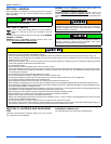
SECTION IX: TORQUE REQUIREMENTS
FOR CAPS AND FASTNERS
When servicing or repairing HVAC components, ensure the fasteners
are appropriately tightened. The table below provides torque values for
fasteners.
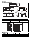
SECTION X: INDOOR UNIT INSTALLATION
INSTALLING THE WALL MOUNTING BRACKET
Determine that the wall will support the weight of the indoor unit. Refer
to system specifications for indoor unit weight. Install the wall mounting
bracket and make sure it's positioned horizontally and vertically. The
indoor unit must be installed level on the wall to allow proper conden-
sate drainage.
1. Determine the best exit location for utility bundle (line set, conden-
sate line and wiring).
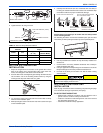
2. Use the wall mounting bracket as a template to determine the exit
point for utility bundle. Use a carpenter's level or tape measure to
verify the wall mounting bracket is horizontally level and mark the
boring points on the wall. See Figure 11.
3. Prior to making the hole and installing wall sleeve for the utility bun-
dle, check to ensure that neither studs nor plumbing are directly
located behind the hole location.
4. Secure the wall mounting bracket to the wall using the provided
screws. If possible, align the rear panel screw holes with wall stud
locations marked on the wall. Make sure you use as many screws
into studs as possible. All other screws must be secured using plas-
tic wall anchors. See Figure 13.
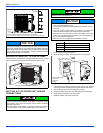
5. If the wall is made of brick, concrete or other similar material, then
drill pilot holes in the wall. Insert field-provided anchors for mount-
ing screws. See Figure 13.
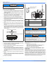
WALL HOLE DRILLING
Be sure to caulk the gaps around the pipes with caulking material to
prevent water leakage.
1. Determine the wall hole position.
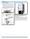
2. Drill a 2-1/2 inch diameter hole in the wall. The hole should be
slightly downward slant 3/16" to 3/8" (5 to 10 mm) lower than the
indoor side.
3. Measure the thickness of the wall from inside to outside edges and
cut field-provided PVC pipe at a slight angle 1/4" (6mm) shorter
than the thickness of the wall.
4. Place a field-provided plastic cover on the outside end of the PVC
pipe and insert the pipe in the wall hole.
5. After completing refrigerant piping, wiring, and drain piping, caulk
pipe hole gap with putty.
SECTION XI: INDOOR UNIT WIRING
CONNECTIONS
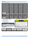
TABLE 9:
Caps and Fasteners Torque Requirements
Parts
Recommended Torque
English
(ft. - lb.)
Metric
(Newton Meter)
Service valve cap 8 ft. - lb. 11
Sheet metal screws 16 ft. - lb. 2
Machine screws #10 27 ft. - lb. 3
Compressor bolts 7 ft. - lb. 10
Gauge port seal cap 8 ft. - lb. 11
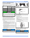
Only use Allen wrenches of sufficient hardness (50Rc - Rockwell
Harness Scale minimum). Fully insert the wrench into the valve stem
recess.
Service valve stems are factory-torqued (from 9 ft-lbs for small
valves, to 25 ft-lbs for large valves) to prevent refrigerant loss during
shipping and handling. Using an Allen wrench rated at less than
50Rc risks rounding or breaking off the wrench, or stripping the valve
stem recess.
It is important to use all screws provided to secure the wall mounting
bracket to the wall. Additional holes may be drilled through the metal
wall mounting bracket to better secure wall bracket to wall studs.
NOTICE
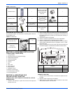
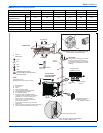
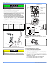
FIGURE 8: Mounting Bracket Spots
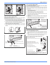
FIGURE 9: Masonry Applications
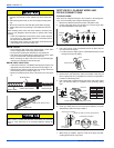
FIGURE 10: PVC Wall Sleeve Installation
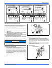
When the indoor unit is powered from the outdoor unit, a dis-
connect switch needs to be installed to power supply circuit
between indoor and outdoor units depending on local codes.
Mark on the middle of it
5.9inch
Left
Space
to the
wall
above
Right
Space
to the
wall
above
5.9inch
WALL
WALL
LEVELING DEVICE
(REAR PIPING HOLE)
(REAR PIPING HOLE)
DRILL PILOT HOLES
USEANCHORS
INSTALLANCHORS
INSIDE
OUTSIDE
CAULKING
2.2”
WALL PIPE
NOTICE