


898841-UIM-B-0113
6 Johnson Controls Unitary Products
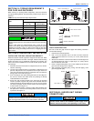
Connecting Wires and the Ground Wire
• Use double insulated copper wire with 600V insulation.
• Use copper conductors only.
• Follow all local electrical codes.
Power Supply Cable and Ground Wire
• Use copper conductors only.
• Follow all local electrical codes.
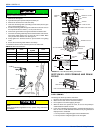
SECTION VII: REFRIGERANT LINE SET
REQUIREMENTS
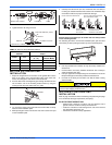
• To prevent condensation, insulate the two refrigerant pipes.
• Refrigerant pipe bending radius must be 4 in. (100 mm) or more.
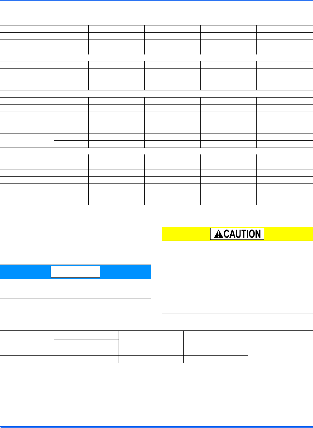
TABLE 4:
Heat Pump Electrical Specifications
INDOOR UNIT
Heat Pumps DHPM09NWM42Q1 DHPM09NWM41Q1 DHPM12NWM42Q1 DHPM12NWM41Q1
Power Supply (V, Phase, Hz) 208/230V/1 115V/1 208/230V/1 115V/1
Min. Circuit Ampacity 10 16 10 16
Fan Motor (F.L.A) 0.2 0.38 0.2 0.38
INDOOR UNIT
Heat Pumps DHPM18NWM42Q1 DHPM24NWM42Q1 DHPM30NWM42Q1 DHPM36NWM42Q1
Power Supply (V, Phase, Hz) 208/230V/1/60HZ 208/230V/1/60HZ 208/230V/1/60HZ 208/230V/1/60HZ
Min. Circuit Ampacity 16A 16A 15 23
Fan Motor (F.L.A) 0.28A 0.24A 0.4 0.47
OUTDOOR UNIT
Heat Pumps DHPM09CSM42Q1 DHPM09CSM41Q1 DHPM12CSM42Q1 DHPM12CSM41Q1
Power Supply (V, Phase, Hz) 208/230V/1 115V/1 208/230V/1 115V/1
Max. Fuse Size (time delay) (A)15251525
Min. Circuit Ampacity 10 16 10 16
Fan Motor (F.L.A) 0.14 0.17 0.14 0.17
Compressor
R.L.A 6.21 12.23 5.34 12.43
L.R.A 13.8 33 13.8 33
OUTDOOR UNIT
Heat Pumps DHPM18CSM42Q1 DHPM24CSM42Q1 DHPM30CSM42Q1 DHPM36CSM42Q1
Power Supply (V, Phase, Hz) 208/230V/1/60HZ 208/230V/1/60HZ 208/230V/1/60HZ 208/230V/1/60HZ
Max. Fuse Size (time delay) (A) 20A 20A 25 35
Min. Circuit Ampacity 16A 16A 15 23
Fan Motor (F.L.A) 0.32A 1.1A 0.45 0.73
Compressor
R.L.A 9.35A 10.45A 11.42 16.95
L.R.A / / / /
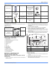
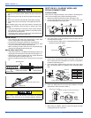
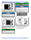
The the indoor unit is powered from the outdoor unit, depending on
local code, a disconnect switch needs to be installed to a power sup-
ply circuit.
NOTICE
Be sure to use the insulation of specified thickness (refer to Table 5).
Excessive insulation may cause incorrect installation of the indoor
unit, and too little insulation may cause condensate to form.
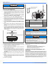
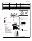
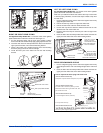
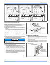
• The unit has flared connections on both indoor and outdoor sides
• Remove the valve cover from the outdoor unit then connect the
pipe
• Refrigerant pipes are used to connect the indoor and outdoor units
• Be careful not to crush or over bend the pipe in pipe bending
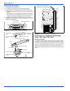
• Refrigerant adjustment
• If pipe length exceeds 25 ft. (7.5 m), additional refrigerant (R410A)
charge is required (The outdoor unit is charged with refrigerant for
pipe length up to 25 ft. [7.5 m]).
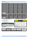
TABLE 5:
Insulation Thickness & Material Information
Pipe
Outside Diameter
Minimum Wall
Thickness
Insulation
Thickness
Insulation
Material
Inch (mm)
Liquid Line .375 (9.52) 0.0315 (0.8) 0.315 (8)
Heat Resistant Foam Plastic
0.045 Specific Gravity
Gas Line .625 (15.9) 0.0394 (1.0) 0.315 (8)