


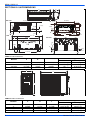
898841-UIM-B-0113
12 Johnson Controls Unitary Products
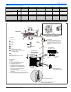
DRAIN PIPING
• If the extension drain hose has to pass through a room, make
sure it's wrapped with commercially sold insulation.
• The drain hose should point downward for easy drain flow.
• If the drain hose provided with the indoor unit is too short, make
sure you connect it with a field-provided drain hose.
• When connecting the drain hose to the hard vinyl chloride pipe,
make sure it's inserted securely into the pipe.
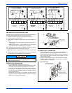
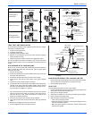
DRAIN HOSE JUNCTION
• If drain hose extension or embedded drain piping is required, use
appropriate parts that match the hose front end. See Figure 18.
• Insert drain hose into the handle of drain pan, and join drain hose
and connecting hose according to Figure 18.
• Attach the Insulation (Drain hose) to the drain hose. See Figure
19.
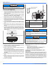
SECTION XIII: FLARING WORK AND
PIPING CONNECTIONS
FLARING WORK
Main cause for refrigerant leakage is due to defect in the flaring work.
Carry out correct flaring work using the following procedure.
1. Measure the distance between the indoor and outdoor units.
2. Cut the copper pipe about 6 to 8 inches (15 to 20 cm) longer than
the measured distance with a pipe cutter.
3. Use a pipe reamer or file to completely remove all burrs from the
cut cross section of the pipe.
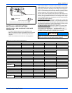
a. Put the end of the copper pipe in a downward direction to avoid
having burrs drop in the piping.
4. Remove flare nuts attached to indoor and outdoor units then put
them on pipes that have completed burrs removal (not possible to
put them on after flaring work).
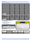
5. Use a flaring tool to perform flaring work at the end of the copper
pipe. Use the table below as a guideline when performing flaring
work.
6. Check your flaring work and if it's found to be defective, cut off the
defective flare section and redo number 5.
7. When flaring is complete, align the center of the pipes and suffi-
ciently tighten the flare nut by hand.
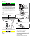
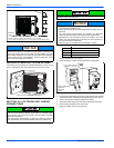
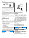
1. In order to align the drain hose and drain cap, be sure to insert
securely and vertically. Incline insertion will cause water leak-
age.
2. After removing drain hose, be sure not to forget mounting drain
cap.
3. Be sure to fix the drain hose with tape to the bottom of piping.
4. Prevent drain water from freezing in low temperature environ-
ment.
When installing indoor unit’s drain hose outdoors, necessary mea-
sure for frost protection should be taken to prevent drain water
freezing.
• Under low temperature environment (when outdoor tempera-
ture under 32 °F), after cooling operation is executed, water in
the drain hose could be frozen.
• Once drain water is frozen, the drain hose will be blocked and
water leakage may result from indoor unit.
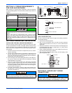
FIGURE 18: Drain Hose Extension
FIGURE 19: Drain Hose Insulation
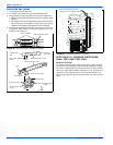
Insert the drain hose and drain cap into the drain port, making sure
that it comes in contact with the back of the drain port, and then
mount it. If the drain hose is not connected properly, leaking will
occur.
SHIELD PIPE
DRAIN HOSE
INSIDE THE ROOM
EXTENSION
DRAIN HOSE
DRAIN HOSE
INSULATION (DRAIN HOSE)
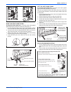
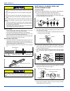
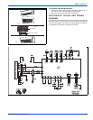
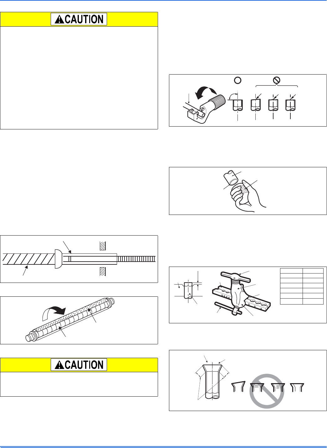
FIGURE 20: Pipe Cutting Approved Method
FIGURE 21: Deburring Line Set
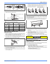
FIGURE 22: Flaring Tools
FIGURE 23: Proper and Improper Flaring
COPPER
PIPE
SLANTED
UNEVEN ROUGH
90°
PIPE
REAMER
POINT DOWN
"A"
BAR
HANDLE
YOKE
CONE
REDARROW MARK
CLAMP HANDLE
COPPER PIPE
BAR
Outside Dia.
Inch
0.24
0.37
0.47
0.63
0.75
A
Inch
0~0.02
~0.02
~0.02
~0.04
~0.05
0
0
0
0.04
SMOOTHALL ROUND
INSIDE IS SHINY WITHOUT SCRATCHES
= IMPROPER FLARING =
EVEN LENGTH
ALL ROUND
INCLINED
SURFACE
DAMAGED
CRACKED
UNEVEN
THICKNESS