


898841-UIM-B-0113
Johnson Controls Unitary Products 17
LEAK TEST AND EVACUATION
Air and moisture remaining in the refrigerant system will have undesir-
able effects as indicated below:
1. Pressure in the system rises.
2. Operating current rises.
3. Cooling or heating efficiency drops.
4. Moisture in the refrigerant circuit may freeze and block capillary
tubing (30 kBtu size only).
5. Water may lead to corrosion of parts in the refrigeration system.
The line set between the indoor and outdoor units must be leak tested
and evacuated to remove any non-condensable and moisture from the
system.
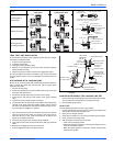
AIR PURGING WITH VACCUM PUMP
Be sure to use a vacuum pump with counter-flow prevention function to
make oil inside the pump does not flow back into the system pipes
when the pump stops.
1. Run the vacuum pump.
2. Connect the charge hose from the manifold valve to the service port
of the gas side packed valve.
3. Connect the charge hose to the port of the vacuum pump.
4. Open fully the low pressure side handle of the gauge manifold
valve.
5. Operate the vacuum pump to begin evacuating.
6. The operation time for evacuation varies with the lineset length and
capacity of the pump. Allow the pumpto operate until the system
has been evacuated downto 300 microns. Allow the pump to con-
tinue running foran additional 15 minutes.
7. Turn off the pump and leave the connection secured to the suction/
vapor 2-way service port. After five minutes, if the system fails to
hold 500 microns or less, check all connections for tight fit and
repeat the evacuation procedure.
8. Close the low pressure valve handle of gauge manifold.
9. Open fully the valve stem of the packed valves (both gas and liquid
sides).
10. Remove the charging hose from the service port.
11. Securely tighten the caps on the packed valves.
ADDING REFRIGERANT FOR LONGER LINE SET
1. Open the low side manifold gauge valve and weigh in liquid refriger-
ant. Use Table 6 to calculate the correct weigh-in charge.
2. Close manifold gauge valves.
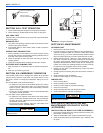
LEAK TEST
Use the following procedure to test for system leaks:
1. Connect the manifold gauge set and dry nitrogen gas cylinder to the
suction/vapor service port. See Figure 30.
2. Open valve on nitrogen cylinder.
3. Pressurize the system to no more than 150 PSIG with dry nitrogen.
4. Check for leaks using soapy water.
5. After the system is found to be free of leaks:
• Close valve on nitrogen cylinder
• Relieve the nitrogen pressure by: loosening the charge hose con-
nector at the nitrogen cylinder.
• When the system pressure is reduced to normal, disconnect the
hose from the cylinder.
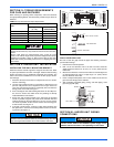
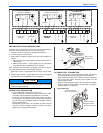
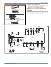
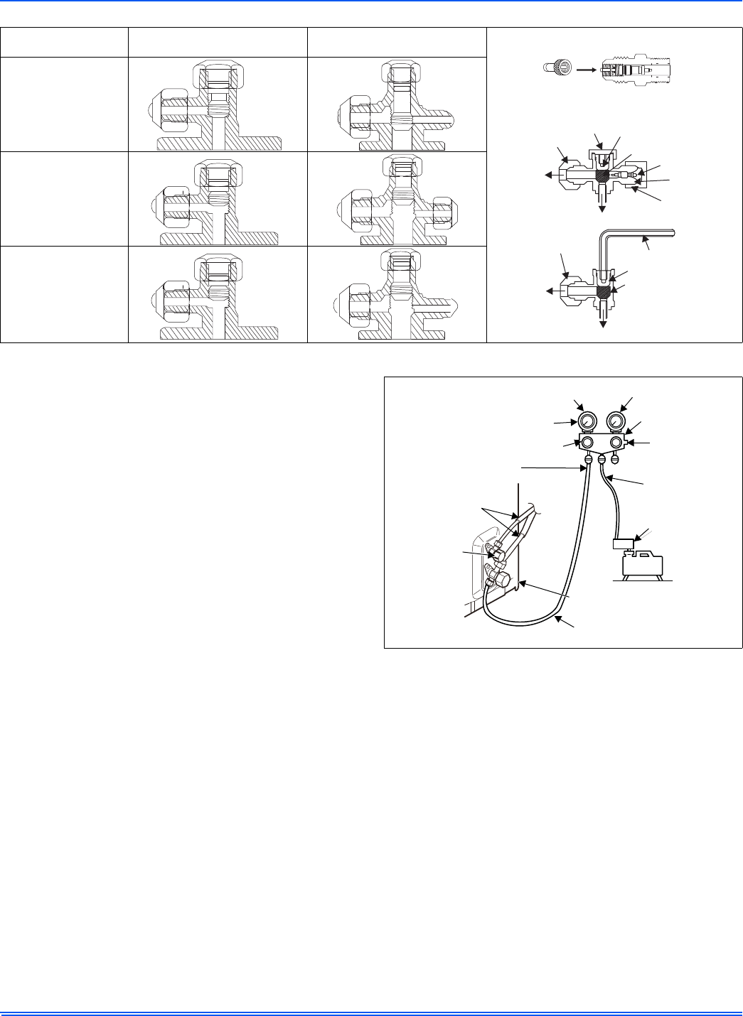
Action
Shut-off
2-way Valve
Suction/Vapor
2-way Service Valve
Evacuating with a
vacuum pump
Outdoor unit running
Checking pressure
and adding refrigerant
FIGURE 38: Service Valve Operation
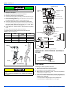
SUCTION/VAPOR
2-WAY SERVICE VALVE
HOSE WITH
SCHRADER VALVE
PUSH
REQUIRES FIELD PROVIDED 5/16” FEMALE
FLARE TO 1/4” MALE FLAREADAPTER.
VALVE CAP
OPEN POSITION
CLOSED POSITION
SCHRADER CORE
FLARE CAP
TO LINE SET
SERVICE
PORT CAP
SERVICE
PORT
TO OUTDOOR UNIT
FLARE CAP
ALLEN WRENCH (5MM)
OPEN POSITION
CLOSED POISTION
TO OUTDOOR UNIT
TO LINE SET
CLOSED
FULLY
OPEN
FULLY
OPEN
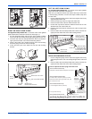
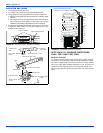
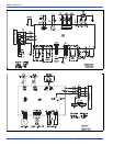
FIGURE 39: Gauge Set Connections for Test Leaks, Evacuation
Charging
COMPOUND
PRESSURE
GAUGE
PRESSURE GAUGE
-101kPa
(-76cmHg)
HANDLE LOW
MANIFOLD VALVE
HANDLE HIGH
(KEEP FULL
CLOSED)
CHARGE HOSE
CHARGE HOSE
CONNECTING
PIPE
PACKED VALVE
ATLIQUID SIDE
VACUUM PUMP
ADAPTER FOR
COUNTER-FLOW
PREVENTION
PACKED VALVEAT GAS SIDE
SERVICE PORT
SCHRADER CORE
VACUUM
PUMP