


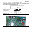
898841-UIM-B-0113
42 Johnson Controls Unitary Products
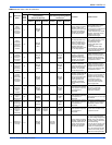
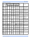
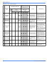
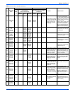
12
Indoor
ambient
temperature
sensor is
open/short
circuited
F1
OFF 3S
and blink
once
During cooling and drying
operation, indoor unit
operates while other loads
will stop; during heating
operation, the complete
unit will stop operation.
1. Loosening or bad contact of
indoor ambient temp. sensor
and mainboard terminal.
2. Components in mainboard fell
down leads short circuit.
3. Indoor ambient temp. sensor
damaged. (check with sensor
resistance value chart).
4. Mainboard damaged.
13
Indoor
evaporator
temperature
sensor is
open/short
circuited
F2
OFF 3S
and blink
twice
AC stops operation once
reaches the setting tem-
perature. Cooling, drying:
internal fan motor stops
operation while other
loads stop operation; heat-
ing: AC stop operation
1. Loosening or bad contact of
Indoor evaporator temp. sensor
and mainboard terminal.
2. Components on the
mainboard fall down leads
short circuit.
3. Indoor evaporator temp.
sensor damaged. (check temp.
sensor value chart for testing).
4. Mainboard damaged.
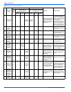
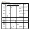
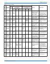
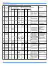
14
Outdoor
ambient
temperature
sensor is
open/short
circuited
F3
OFF 3S
and blink
3 times
OFF 3S
and blink
6 times
During cooling and drying
operating, compressor
stops while indoor fan
operates; During heating
operation, the complete
unit will stop operation.
Outdoor temperature sensor
hasnt been connected well or is
damaged. Please check it by
referring to the resistance table
for temperature sensor).
15
Outdoor
condenser
temperature
sensor is
open/short
circuited
F4
OFF 3S
and blink
4 times
OFF 3S
and blink
5 times
During cooling and drying
operation, compressor
stops while indoor fan will
operate; During heating
operation, the complete
unit will stop operation.
Outdoor temperature sensor
hasnt been connected well or is
damaged. Please check it by
referring to the resistance table
for temperature sensor).
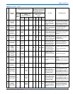
16
Outdoor
discharge
temperature
sensor is
open/short
circuited
F5
OFF 3S
and blink
5 times
OFF 3S
and blink
7 times
During cooling and drying
operation, compressor will
stop after operating for
about 3 mins,while indoor
fan will operate;During
heating operation, the
complete unit will stop
after operating for about
3 mins.
1.Outdoor temperature sensor
hasnt been connected well or is
damaged. Please check it by
referring to the resistance table
for temperature sensor).
2.The head of temperature
sensor hasnt been inserted
into the copper tube.
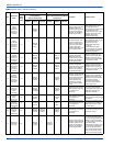
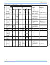
17
Limit/
decrease
frequency
due to
overload
F6
OFF 3S
and blink
for 6 times
OFF 3S
and blink
3 times
All loads operate normally,
while operation frequency
for compressor is
decreased.
Refer to the ProficienTECH
Ductless Splits Technical Train-
ing Manual (overload, high
temperature resistant)
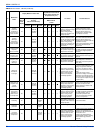
18
Decrease
frequency
due to
overcurrent
F8
OFF 3S
and blink
8 times
OFF 3S
and blink
once
All loads operate normally,
while operation frequency
for compressor is
decreased.
The input supply voltage is too
low; System pressure is too high
and overload.
19
Decrease
frequency
due to high
air discharge
F9
OFF 3S
and blink
9 times
OFF 3S
and blink
twice
All loads operate normally,
while operation frequency
for compressor is
decreased.
Overload or temperature is too
high; Refrigerant is insufficient;
Malfunction of electric expan-
sion valve (EKV).
20
Limit/
decrease
frequency
due to
antifreezing
FH
OFF 3S
and blink
2 times
OFF 3S
and blink
2 times
OFF 3S
and blink
4 times
All loads operate normally,
while operation frequency
for compressor is
decreased.
Poor air-return in indoor unit or
fan speed is too low.
21
Voltage for
DC bus-bar is
too high
PH
OFF 3S
and blink
11 times
OFF 3S
and blink
13 times
During cooling and drying
operation, compressor will
stop while indoor fan will
operate; During heating
operation, the complete
unit will stop operation.
1. Measure the voltage of posi-
tion L and N on wiring board
(XT), if the voltage is higher than
265VAC, turn on the unit after
the supply voltage is increased
to the normal range.
2.If the AC input is normal, mea-
sure the voltage of electrolytic
capacitor C on control panel
(AP1), if its normal, theres mal-
function for the circuit, please
replace the control panel (AP1).
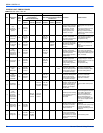
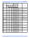
TABLE 14:
Error Codes - 30K 36K (Continued)
No.
Malfunction
Name
Display Method of Indoor Unit Malfunction
A/C Status Possible Causes
Dual 8
Code
Display
Indicator Display
(during blinking,
ON 0.5s and OFF 0.5s)
Indicator has 3 kinds of display
status and during blinking, ON 0.5s
and OFF 0.5s
Operation
Indicator
Cool
Indicator
Heating
Indicator
Yellow
Indicator
Red
Indicator
Green
Indicator