


898841-UIM-B-0113
Johnson Controls Unitary Products 5
SECTION VI: SPECIFICATIONS
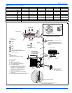
POWER SUPPLY AND INDOOR/OUTDOOR WIRE
CONNECTION
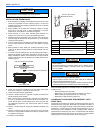
• The system should be powered from a dedicated circuit.
• Wiring work should be based on applicable technical standards.
• Wiring connections should be made following the provided
diagrams.
• Make sure all electrical connections are securely tightened.
Solid conductor AWG14 or stranded conductor AWG14 are the MINI-
MUM allowable wire sizes. There are some applications that will require
larger gauge conductors depending on the voltage and amperage rat-
ings on the data plate and the distance that the conductors will be
routed. It is the installing contractor's responsibility to properly size the
electrical conductors for the equipment and for the application.
All of the indoor units and outdoor units should have the electrical con-
ductors sized using the National Electrical Code (NEC) and the local
authority having jurisdiction whichever is more stringent. If the equip-
ment is installed outside of the United States, all local codes within the
country of origin must be followed.
The Ductless indoor units
must have a minimum of 14 gauge, 600
volt double insulated copper conductors. The conductors for the indoor
unit can be either solid or stranded copper. When possible the indoor
unit should have stranded wire for the communication to ensure proper
communication between the indoor and outdoor unit(s).
The Ductless outdoor units
must have a minimum of 12 gauge, 600
volt double insulated copper conductors with the exception of the fol-
lowing models: DHPM30CSM42Q1, DHPM36CSM42Q1, and
DCPM36CSM42Q1, which require 10 gauge wire. The conductors for
the outdoor unit should be solid or stranded copper conductors.
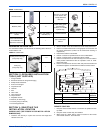
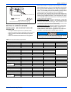
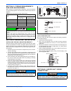
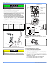
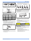
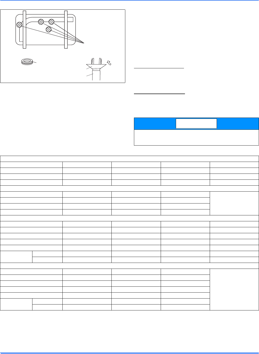
FIGURE 4: Condensate Drainage
DRAIN-WATER HOLE
BOTTOM FRAME
DRAIN PLUG
DRAIN CONNECTOR
HOSE (available commerially, inner dia. 0.63”)
The listed wire sizes are only minimum requirements, as previously
stated, the conductors for both indoor and outdoor units must be
sized using the NEC and local authority having jurisdiction.
NOTICE
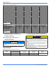
TABLE 3:
Air Conditioner Electrical Specifications
INDOOR UNIT
Air Conditioners DCPM09NWM42Q1 DCPM09NWM41Q1 DCPM12NWM42Q1 DCPM12NWM41Q1
Power Supply (V, Phase, Hz) 208/230V/1 115V/1 208/230V/1 115V/1
Min. Circuit Ampacity 10 16 10 16
Fan Motor (F.L.A) 0.2 0.38 0.2 0.38
INDOOR UNIT
Air Conditioners DCPM18NWM42Q1 DCPM24NWM42Q1 DCPM36NWM42Q1
Power Supply (V, Phase, Hz) 208/230V/1/60HZ 208/230V/1/60HZ 208/230V/1/60HZ
Min. Circuit Ampacity 16 16 17
Fan Motor (F.L.A) 0.28 0.24 0.4
OUTDOOR UNIT
Air Conditioners DCPM09CSM42Q1 DCPM09CSM41Q1 DCPM12CSM42Q1 DCPM12CSM41Q1
Power Supply (V, Phase, Hz) 208/230V/1 115V/1 208/230V/1 115V/1
Max. Fuse Size (time delay) (A) 15 25 15 25
Min. Circuit Ampacity 10 16 10 16
Fan Motor (F.L.A) 0.14 0.17 0.14 0.17
Compressor
R.L.A 6.21 12.23 5.34 12.43
L.R.A 13.8 33 13.8 33
OUTDOOR UNIT
Air Conditioners DCPM18CSM42Q1 DCPM24CSM42Q1 DCPM36CSM42Q1
Power Supply (V, Phase, Hz) 208/230V/1/60HZ 208/230V/1/60HZ 208/230V/1/60HZ
Max. Fuse Size (time delay) (A) 20 20 25
Min. Circuit Ampacity 16 16 17
Fan Motor (F.L.A) 0.32 1.1 0.45
Compressor
R.L.A 9.35 10.45 12.66
L.R.A///