


9
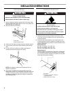
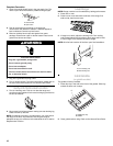
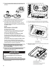
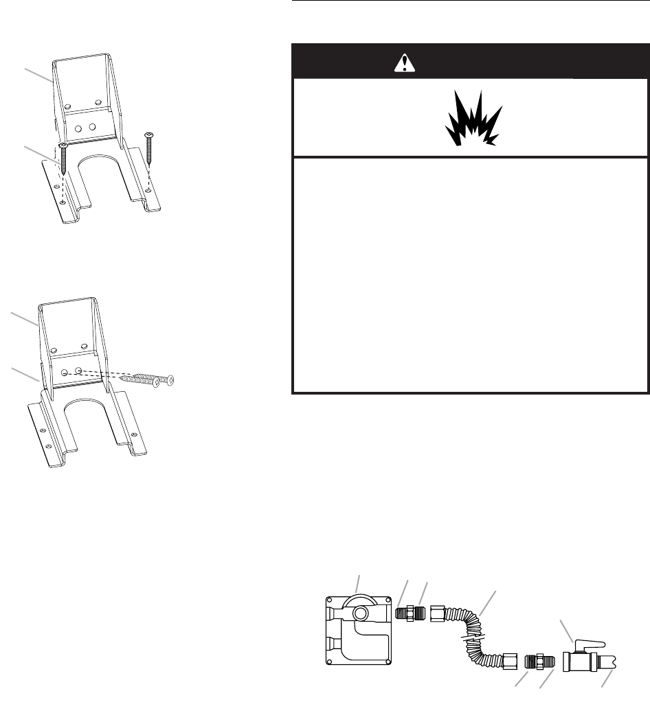
3. Drill two ¹⁄₈" (3.0 mm) holes that correspond to the bracket
holes of the determined mounting method. See the following.
Floor Mounting
Wall Mounting
4. Using a Phillips screwdriver, mount anti-tip bracket to the wall
or floor with the two #12 x 1⁵⁄₈" screws provided.
Depending on the thickness of your flooring, longer screws
may be necessary to anchor the bracket to the subfloor.
Longer screws are available from your local hardware store.
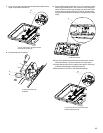
5. Move range close enough to opening to allow for electrical
connections to be made. Remove shipping base, cardboard
or hardboard from under range.
6. Continue installing your range using the following installation
instructions.
Make Gas Connection
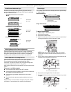
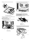
1. Assemble flexible connector from gas supply pipe to pressure
regulator located in the middle rear of the range.
2. Apply pipe-joint compound made for use with LP gas to the
smaller thread ends of the flexible connector adapters (see B
and G in the following illustration).
3. Attach one adapter to the gas pressure regulator and the
other adapter to the gas shutoff valve. Tighten both adapters.
4. Use a ¹⁵⁄₁₆" combination wrench and channel lock pliers to
attach the flexible connector to the adapters. Check that
connector is not kinked.
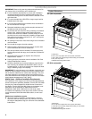
A. #12 x 1⁵⁄₈" screws
B.Anti-tip bracket
A.#12 x 1⁵⁄₈" screws
B.Anti-tip bracket
B
A
B
A
A.Gas pressure regulator
B.Use pipe-joint compound.
C. Adapter (must have ½" male
pipe thread)
D.Flexible connector
E. Manual gas shutoff valve
F. ½" or ¾" gas pipe
G. Use pipe-joint compound.
H.Adapter
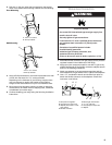
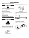
WARNING
Explosion Hazard
Use a new CSA International approved gas supply line.
Install a shut-off valve.
Securely tighten all gas connections.
If connected to LP, have a qualified person make sure
gas pressure does not exceed 14" (36 cm) water
column.
Examples of a qualified person include:
licensed heating personnel,
authorized gas company personnel, and
authorized service personnel.
Failure to do so can result in death, explosion, or fire.
A
B
C
D
E
FG
H