


20
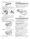
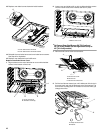
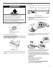
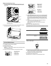
13. Open the oven door and remove the 2 screws on each side of
the range that hold the control console in place.
NOTE: Make sure to leave oven door open or the control
console will not rest in the side brackets properly once it is
detached.
14. Pull up on the control console and let it drop forward into the
notched console brackets on each side.
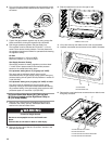
15. Remove the round gasket from the valve stem.
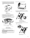
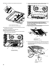
16. Use a ¹⁄₈" x 4¼" flat-blade screwdriver to completely screw
down all burner screws.
17. Replace the round gasket.
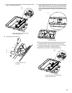
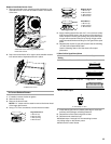
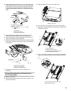
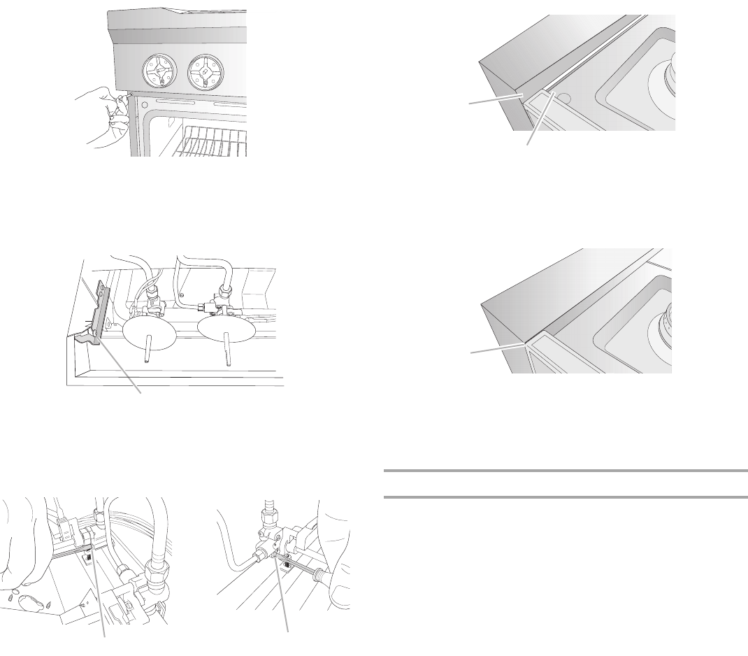
18. Lift up on the control console and set it back into place. For a
proper fit, the flange of the control console must hook over
the lip on the front of the range cooktop.
19. Check that the control console is flush with the top edge of
the range.
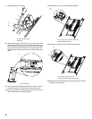
20. Replace the 2 screws on each side of the control console.
21. Replace the control knobs.
22. Replace burner grates.
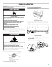
Complete Installation
1. Refer to the “Make Gas Connection” section for properly
connecting the range to the gas supply.
2. Refer to the “Electronic Ignition System” section for proper
burner ignition, operation, and burner flame adjustments.
IMPORTANT: You may have to adjust the “LO” setting for
each cooktop burner.
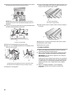
Checking for proper cooktop burner flame is very important.
The small inner cone should have a very distinct blue flame
¼" (0.64 cm) to ½" (1.3 cm) long. The outer cone is not as
distinct as the inner cone. LP gas flames have a slightly
yellow tip.
3. Refer to “Complete Installation” in the “Installation
Instructions” section of this manual to complete this
procedure.
A.Control console bracket
A.Single flame burner adjustment screw (on right side of valve)
B.Dual flame burner adjustment screw (on left side of valve)
A
A
B
A. Control console flange
B. Front lip of range cooktop
A. Flush with range top
A
B
A