


28
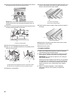
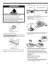
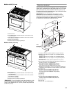
Complete Installation
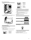
1. Refer to the “Make Gas Connection” section for properly
connecting the range to the gas supply.
2. Refer to the “Electronic Ignition System” section for proper
burner ignition, operation, and burner flame adjustments.
IMPORTANT: You may have to adjust the “LO” setting for
each cooktop burner.
Checking for proper cooktop burner flame is very important.
The small inner cone should have a very distinct blue flame
¼" (0.64 cm) to ½" (1.3 cm) long. The outer cone is not as
distinct as the inner cone. LP gas flames have a slightly
yellow tip.
3. Refer to “Complete Installation” in the “Installation
Instructions” section of this manual to complete this
procedure.
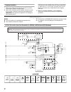
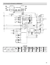
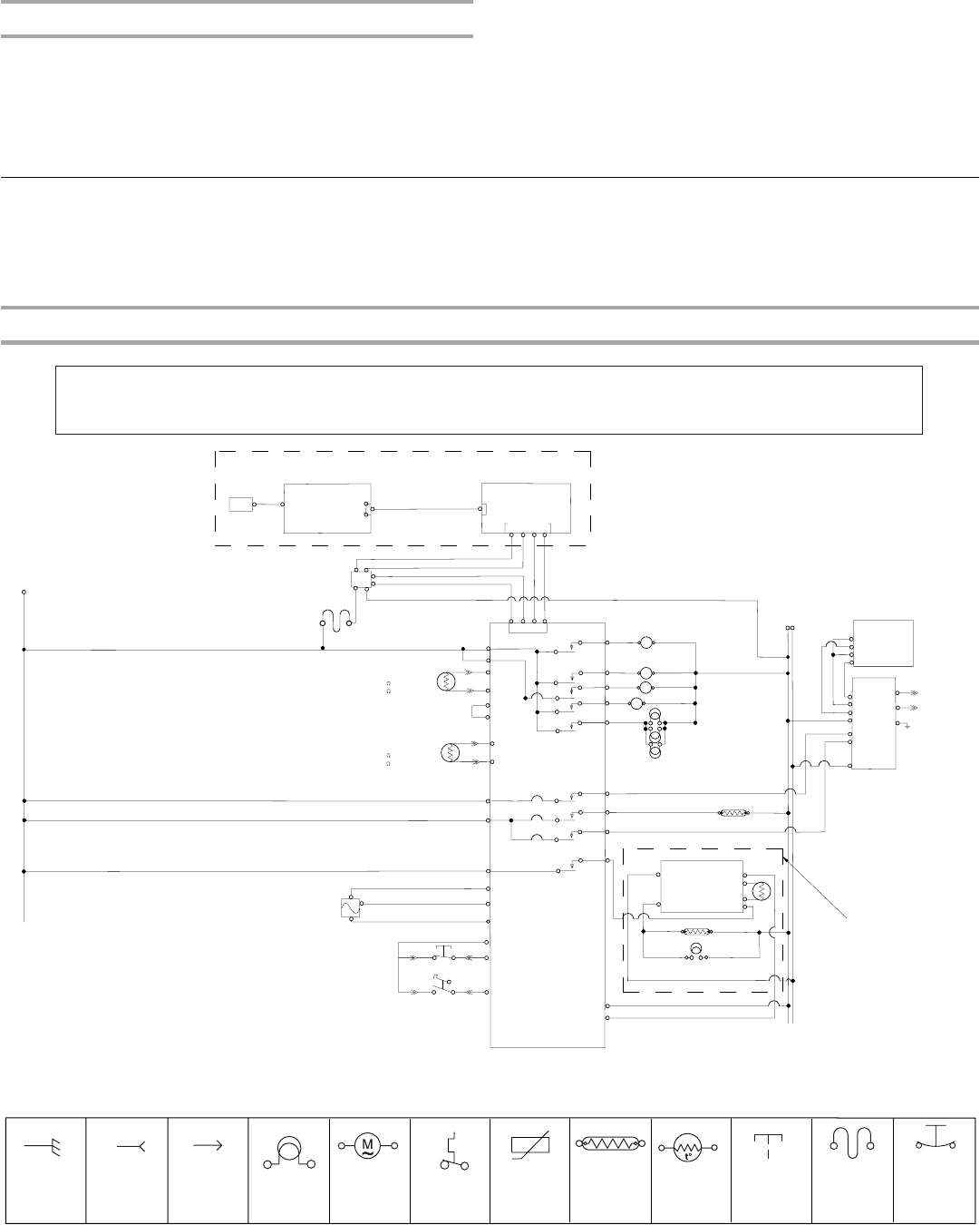
Wiring Diagrams
NOTES:
■ End of line tester is for manufacturing purposes only.
■ Dots indicate connections or splices.
■ Circuit shown in STANDBY/OFF mode with oven door closed.
■ All voltages in the wiring diagrams are designated as
120 VAC.
.30"/36" (76.2 cm/91.4 cm) Oven Schematic for JGRP430, JGRP436 and JGRP536 Models
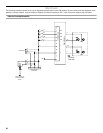
Caution: Label all wires prior to disconnection when servicing controls. Wiring errors can cause improper and dangerous operation.
Verify proper operation after servicing.
P6-4
P6-2
P8-6
P8-5
P8-4
P3-3
P9-2
P3-4
LS Cooling Fan
P3-5
P9-5
P6
Appliance Manager
P8-1
P8-3
Halogen Oven Light
P6-1
P6-5
R
SMPS 14 VDC 45W
M
~
HMI Keyboard
15-pin
ATLAS
LCD
BK
Y
BK
OR
BK
R
Y
Y
BU
Latch Motor
BU
15-pin
Y
P7-3
P7-1
Temp Sensor
1080
AT 21˚C (70 ˚F)
1654
AT 177˚C (350˚F)
V
V
P2-1
W
W
P2-2
t˚
P1-7
Latch Switch (operated by motor)
Door Switch (on latch assy)
P1-5
P1-4
BR
OR
T
BU
BU
BR
BR
T
OR
Strobe
Convect Fan
W
BK
BK
N
W
Hall Sense
L1
BK
BK
BK
BK
BK
BK
W
R/W
T3-1
T3-3
T3-2
T4-3
T4-4
Y
T4-2
M
~
M
~
HS Cooling Fan
W
BU/W
J1-3
J1-4
J2-2
J2-5
J2-4
J2-1
M
~
Conv-1200W
OR
BR
J4-7
J4-8
J4-11
J4-12
BU
J900-1
J900-11
Gas Valve
Common
Broil Solenoid
Common
Bake Solenoid
DSI
J1-1
J1-2
J1-3
J1-4
J1-5
J1-6
J1-7
J1-8
J1-9
J1-10
Griddle Control
P2-1
P2-6
P1-1
P1-3
P1-4
P1-6
Griddle-1320W
T5-2
Griddle Light
L1
BK
Meat Probe
P2-5
W
W
AT 15.6˚ C (60˚ F)
AT 32.2
˚C (90 ˚ F)
P2-6
OR
W
t˚
R/W
OR
BU/W
W
BK
BK
BK
T
BK
T
B
W
W
W
V
R
P2-3
P2-4
OR
36" (91.4 cm)
model only
Broil Burner Igniter
Bake Burner Igniter
78K
37K
Bake
Broil
J3
J4
J2
User Interface (UI)
BK
Thermal Cutoff
(non-resettable)
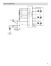
LEGEND
Ground
(Chassis)
Plug With
Female
Connector
Receptacle
With Male
Connector
Light
Thermal Cutoff
(Non-
Resettable)
Operated
By Door
AC Drive
Motor
Enclosed
Thermistor
Heating
Element
Thermo-
actuator
Thermal Cutoff
(manually
Resettable)
Thermostat