


GENERAL
9
Concord CXSi/H - Installation & Servicing
CHIMNEY SYSTEM
To ensure the safe and satisfactory operation of the boiler then the
chimney system (which may be common or individual, in the case
of twin or multiple boiler installations) must be capable of the
complete evacuation of combustion products at all times. The
effective height of the chimney terminal(s) above the boiler outlet(s)
must ensure sufficient buoyancy to overcome the resistance of the
bends, tees and runs of the flue pipe involved and shall terminate in
a down draught free zone. The number of bends and lengths of
horizontal flue pipe used should be kept to a minimum in order to
reduce gas flow resistance.
Compliance with the recommendations made in BS.6644,
IGE UP/10 Installation of Gas Appliances in Industrial and
Commercial Premises and the 'Third Edition of the 1956 Clean
Air Act Memorandum' should be strictly observed where
applicable.
The chimney design should avoid the formation of excessive
quantities of condensate. For this reason it is recommended that all
chimneys are insulated and lined. In the case of brick or similar
structures a stainless steel rigid or flexible flue liner (grade 304/
316) may be used in conjunction with a 50 mm (minimum) thick
layer of vermiculite or perlite granules between the liner and the
inner skin of the chimney body. Liners should be sealed at both top
and bottom.
As the Concord CXSi/H range of boilers is supplied complete with
an integral draught diverter, a diverter MUST NOT be fitted within
the chimney system.
Drainage points positioned at the bottom of all vertical chimney
sections should be provided. Drain pipes should be no less than
25 mm I.D., manufactured from acid condensate resistant material
such as stainless steel and be positioned so that pipe runs and
discharge points are not subject to the effects of frost and that flue
gases cannot leak into the boiler room.
Care should be taken to ensure the specification of the chimney is
suitable for the application by reference to the manufacturers
literature. Caradon Ideal Limited can offer advice on the design of
suitable chimney systems.
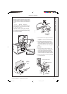
GAS SUPPLY
If there is any doubt regarding the capacity of the gas meter, the
available gas pressure, the adequacy of existing service pipes or
the size required for new service pipes then the advice of the gas
supplier should be requested.
Installation pipework should be fitted and tested for gas soundness
in accordance in accordance with BS. 6891;
IGE-UP-1 for small installations
IGE-UP-2 for large installations.
The local gas supplier must be consulted if it is necessary to employ
a gas pressure booster.
ELECTRICAL SUPPLY
WARNING. This appliance must be efficiently earthed.
A 230 V - 50 Hz mains supply is required, fused at 5 amps.
Wiring external to the appliance MUST be in accordance with the
I.E.E. (BS. 7671) Wiring Regulations and any local regulations
which apply.
For details of connections see Frame 14.
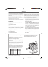
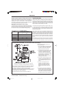
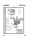
FOUNDATION
The boiler must stand on a non-combustible floor (i.e. concrete
or brick) which must be flat, level and of a suitable load bearing
capacity to support the weight of the boiler (when filled with
water) and any ancillary equipment.
If the boiler is mounted on a plinth then the dimensions must
exceed the plan area of the boiler by at least 75mm on each side.
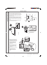
VENTILATION
Safe, efficient and trouble-free operation of conventionally flued gas
boilers is vitally dependent on the provision of an adequate supply
of fresh air to the room in which the appliance is installed. Ventilation
by grilles communicating directly with the outside air is required at
both high and low levels. The minimum free areas of these grilles
must be according to the following scale:
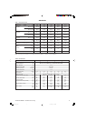
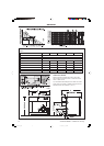
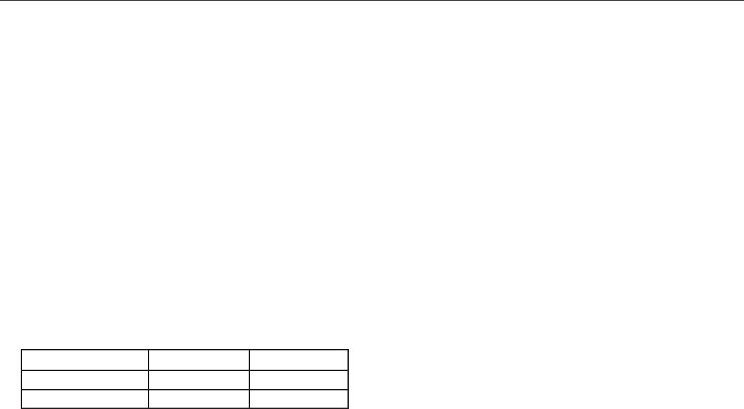
Table 5 - Ventilation Requirements
Required area (cm
2
) per kW of total rated input (net)
Boiler room Enclosure
Low level (inlet) 4 10
High level (outlet) 2 5
Note: Where a boiler installation is to operate in summer
months (e.g. DHW) additional ventilation requirements
are stated, if operating for more than 50% of time (refer
to BS6644).
Position ventilation grilles to avoid the risk of accidental obstruction
by blockage or flooding. If further guidance on ventilation is required
then consult BS.6644.
AIR SUPPLY BY MECHANICAL VENTILATION
The supply of air by mechanical means to a space housing the
boiler should be by mechanical inlet with natural or mechanical
extraction. Mechanical extract ventilation with natural inlet must not
be used.
Where a mechanical inlet and a mechanical extract system is
applied, the design ventilation flow rates should be as in Table 4 of
BS.6644.
The requirements for air supply by mechanical ventilation are given
in BS.6644.
Note. For mechanical ventilation systems an automatic control
should be provided to cause safety shutdown or lockout of the
boiler(s) in the event of failure of air flow in either inlet or extract
fans.
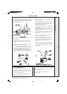
IMPORTANT.
The use of an extractor fan in the same room as the boiler (or in an
adjacent communicating room) can, in certain conditions, adversely
affect the safe operation of the boiler. Where such a fan is already
fitted (or if it is intended to fit an extractor fan after installation of the
appliance) the advice of the gas supplier should be obtained.
Tests for spillage of products from the draught diverter when the
extractor fan is running and all doors and windows are shut should
be carried out after installation. If spillage is detected, the area of
permanent ventilation must be increased.
157294-3.pmd 11/8/2005, 9:58 AM9