


SERVICING
26
Concord CXSi/H - Installation & Servicing
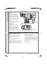
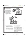
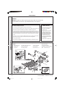
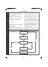
1. Remove the burner tray from
the boiler, as described in
Frames 27-28.
2. Each burner can be removed
by lifting it at the back and
pushing it backward to clear
the injector. Disconnect the
spark electrode assembly and
heat shield from the RH
burner (or the flame detector
electrode from the LH burner),
as necessary.
3. Reassemble in reverse order.
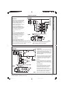
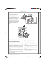
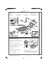
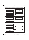
1. Undo and pull off all the plugs from the gas valve solenoids.
2. Turn off the gas at the gas inlet cock. Undo the 2 unions at either side of the gas valve
assembly and remove the assembly (complete) to a suitable working area.
3. In order to be able to remove the faulty gas valve it will be necessary to slacken or
remove all the screws on either the inlet or the outlet manifold and only those 4 screws
securing the faulty gas valve on the other manifold. The faulty gas valve can then be
removed and replaced. Ensure that the arrow on the gas valve points in the direction
of flow.
4. Ensure that new ‘O’ ring seals are fitted and that the 'O' ring seals on the remaining
gas valves are correctly in place. Ensure that all screws are retightened.
5. Test for gas soundness.
6. Recommission the appliance and set the manifold pressure, as described in Frame 21.
29
GAS CONTROL VALVE
31
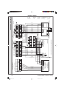
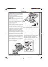
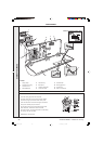
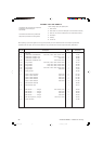
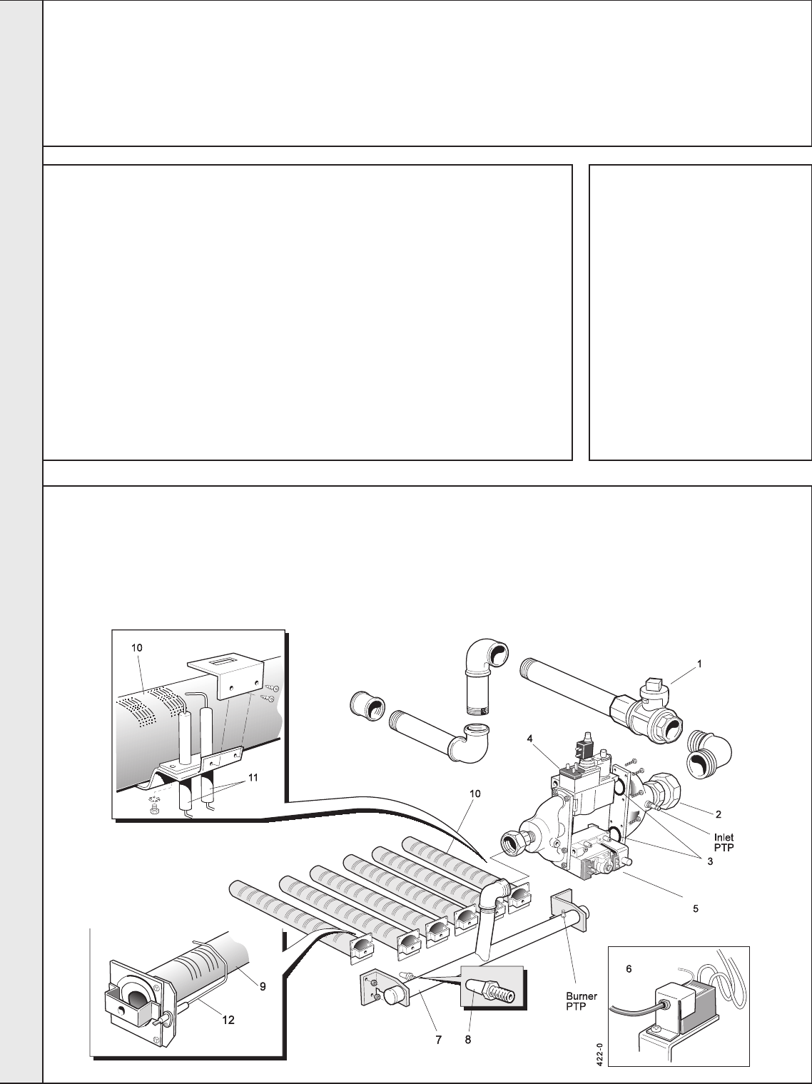
BURNER AND CONTROLS ASSEMBLY - Exploded View - CXSi 110/H - 160/H
7. Burner manifold.
8. Main injector.
9. Main burner - LH.
LEGEND
1. Main gas inlet cock.
2. Gas inlet union.
3. 'O' ring seal.
4. High/Low gas control valve
5. Gas control valve.
6. Spark generator.
10.Main burner RH.
11. Ignition electrodes.
12.Detection electrode assembly.
PTP Pressure test point.
30
MAIN BURNER
GENERAL
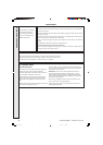
WARNING. ALWAYS turn OFF the gas supply at the gas inlet cock and switch OFF
and DISCONNECT the electricity supply BEFORE working on the appliance.
28
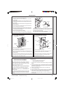
REPLACEMENT OF COMPONENTS - Refer to Frames 5, 31 and 32
SERVICING
157294-3.pmd 11/8/2005, 9:59 AM26