


SERVICING
29
Concord CXSi/H - Installation & Servicing
39
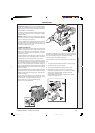
COMBUSTION CHAMBER
INSULATION REPLACEMENT
The insulation boards used in the combustion chambers
of these products contain man-made fibres, refractory
fillers, organic and inorganic binders and as such are
deemed to be harmless to humans.
Caradon Ideal Limited, however, recommend that for
your own comfort and to comply with good working
practise the procedure described below is followed.
IMPORTANT. Turn OFF the gas and DISCONNECT the
electricity supply.
To replace the insulation boards the major boiler
components (including the heat exchanger and burners)
have to be removed to gain access to the combustion
chamber.
Prior to removal of the boards the following protective equipment
should be worn:
• Face mask supplied with the spare part.
• Gloves supplied with the spare part.
1 Damp down the combustion chamber area containing the insulation
boards.
2. Remove the insulation boards. The replacement boards are supplied
in a plastic bag. This bag should be retained and the discarded boards
should now be placed into it.
3. Sweep any dampened particles and place in the plastic bag.
4. Fit new insulation boards.
5. Remove the gloves and face mask and place them in the plastic bag.
6. Wash your hands and any areas of skin which may have come into
contact with any of the particles from the insulation board.
7. Seal the plastic bag and dispose of it and its contents into a
commercial tip.
36
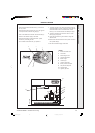
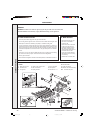
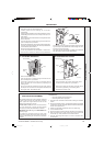
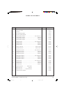
CONTROL SENSOR POTENTIOMETER ASSEMBLY
1. Prise the front cap from the thermostat knob.
2. Carefully loosen the brass retaining nut one full turn
anticlockwise
3. Gently pull the thermostat knob from the potentiometer. When
reassembling ensure the arrow on the body is lined up in the
OFF position.
4. Remove the back nut and brass washer securing the thermostat
knob to the panel.
5. Undo and remove the 2 screws securing the control box front
panel. Carefully lift it up and lower it.
6. Remove the terminal plugs from the back of the potentiometer.
7. Undo the purse clips holding the wires from the potentiometer
to the PCB then pull the wires out.
8. Remove the connections from the PCB.
9. Fit the new potentiometer and reassemble in reverse order.
Ensure that the connections to the back of the potentiometer
37
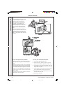
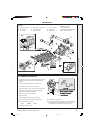
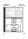
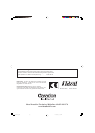
PC BOARD S4561B1047
1. Remove the lower front panel.
2. Undo and remove the 2 screws securing the control box front
panel. Carefully lift it up and lower it.
3. Pull off the 2 plugs and the 2 push-on connections from the
board. The board can now be removed by squeezing in the
retaining barbs.
4. Fit the new board and reassemble in reverse order, ensuring
that the push-on connections are correctly fitted, as follows (from
left to right): Earth - flame detector lead.
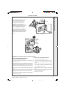
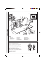
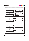
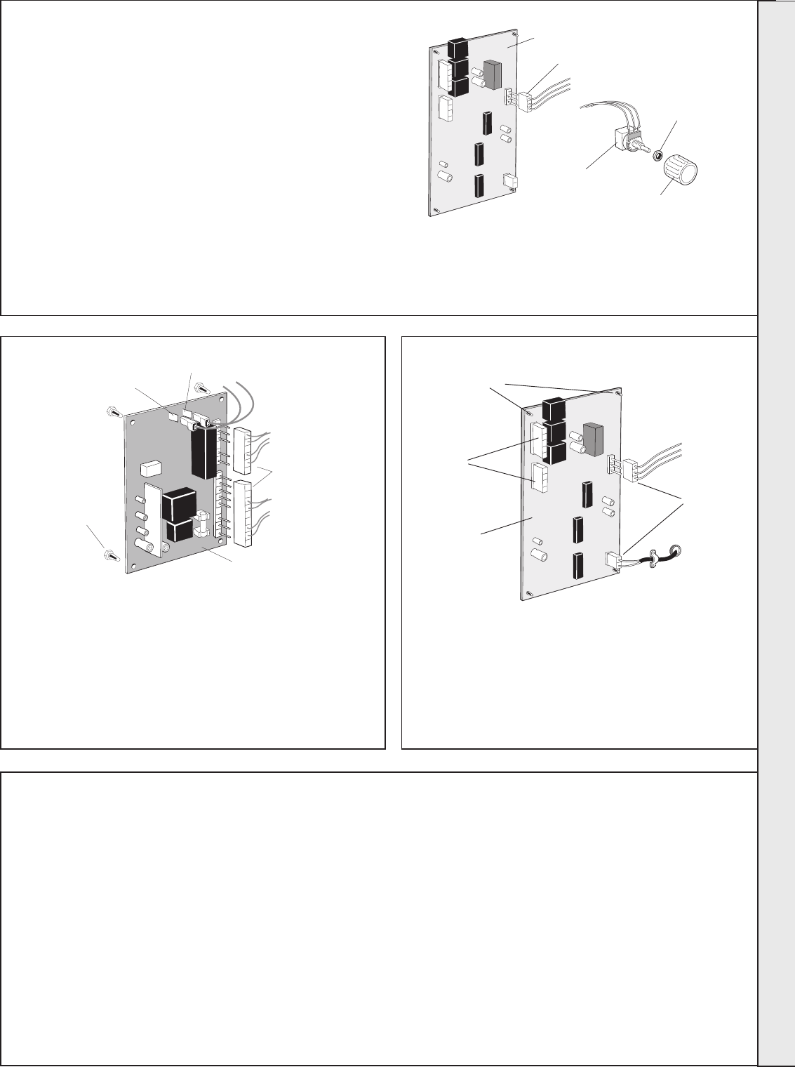
1. Remove the lower front panel.
2. Undo and remove the 2 screws securing the control
box front panel. Carefully lift it up and lower it .
3. Remove the 4 plugs from the board. The board can now
be removed by squeezing in the retaining barbs.
4. Reassemble in reverse order.
38
PC BOARD W4115A1020
are made either to the top 2 tags or the bottom 2 tags and that the
lug on the body of the potentiometer locates through the hole in
the front panel of the control box.
Also ensure that the potentiometer is rotated fully anticlockwise
and clicks before commencing the reassembling.
PCB
Retaining barbs
Con 1910
Plugs
Plugs
Con 1500
PCB
Plug
Potentiometer
Backnut
Thermostat knob
Earth connection
Flame detector connection
PCB
Retaining
barbs
Con 1910
Plugs
SERVICING
157294-3.pmd 11/8/2005, 9:59 AM29