


INSTALLATION
17
Concord CXSi/H - Installation & Servicing
14
ELECTRICAL CONNECTIONS
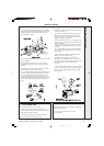
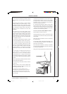
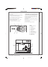
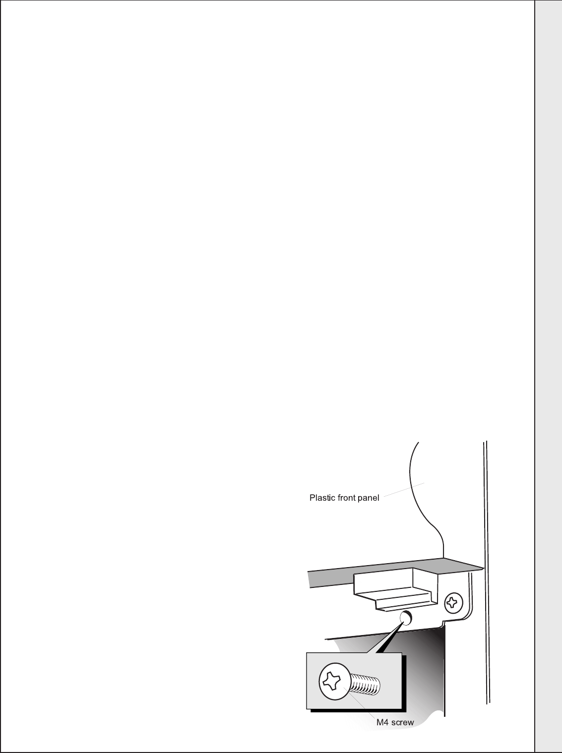
To gain access to the inside of the control box remove
the 2 M4 screws, lift up the plastic front panel and
lower.
Connection must be made in a way that allows
complete isolation of the electrical supply - such as
a double pole switch, having a 3mm (1/8") contact
separation in both poles, or a plug and socket serving
only the boiler and system controls. The means of
isolation must be accessible to the user after
installation.
This should serve only the boiler, together with its
controls and pumps. The unswitched live supply,
which the boiler requires to allow the pump overrun
facility to operate, should be controlled by the above
switched/fused supply, but should connect from there
directly to the boiler and not via any automatic time
or temperature controls.
The switched live supply should be subject to control
by time and temperature controls in the usual way.
The controls incorporate a pump overrun facility, which
is necessary to dissipate residual heat on plant
shutdown. It is essential therefore that the main pump
(and shunt pump if fitted) is wired to the pump
terminals marked L2, N and Earth on the plug-in
terminal strip on the top box at the rear of the control
box.
The main supply to the boiler must be wired to the
boiler terminals L1, N and Earth on the plug-in
terminal strip. This live connection must be
UNSWITCHED, that is a supply not interrupted by
any automatic temperature or time control, to enable
the pump overrun (and the frost protection facility) to
operate.
Failure to operate this procedure will result in nuisance
overheat thermostat operation.
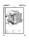
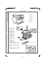
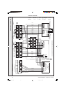
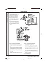
The internal wiring of the boiler control box is shown
in Frame 15.
Wiring should be in four core PVC insulated cable,
not less than 0.75mm
2
(24/0.2mm). All fuses must
be ASTA approved to BS. 1362.
The length of the conductor between the cord
anchorage and the terminals must be such that the
current carrying conductors become taut before the
earthing conductor, if the cable or cord slips out of the
cord anchorage.
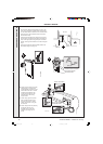
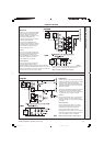
The boiler can be controlled either by volt-free external contacts
connected between terminals X1 and X2 or by a switched
live supply brought to X2 (after removal of the factory-fitted
link between X1 and X2), accompanied in each case by a
permanent live supply to terminal L1.
If a separate frost thermostat is fitted it must be wired
across the time switch contacts and if frost is likely the
system should be turned off using the time switch settings
- all other controls including the boiler thermostat knob
should be in the normal running position.
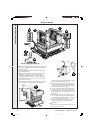
The earth connections MUST NEVER be omitted.
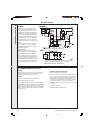
Wire the earths as shown in Frame 13.
All wiring between entry at the rear of the boiler and the
connection box must be secured neatly under the cable
clips provided.
Wiring must never be allowed to come into contact with
the hot boiler body.
If a flow switch is fitted, it should be wired between F
1
and
F
2
on the terminal plug-in connection on the bottom box
at the rear of the control box.
Do not wire these connections in conduit up to the boiler
as this will make it impossible to remove the control box
for servicing or maintenance.
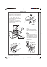
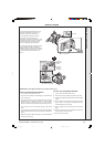
Finally, fit the casing top panel and push down to locate.
Con 1907
INSTALLATION
157294-3.pmd 11/8/2005, 9:59 AM17