


INSTALLATION
12
Concord CXSi/H - Installation & Servicing
7
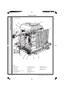
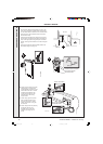
BOILER SECTION ASSEMBLY - continued
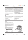
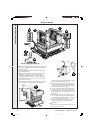
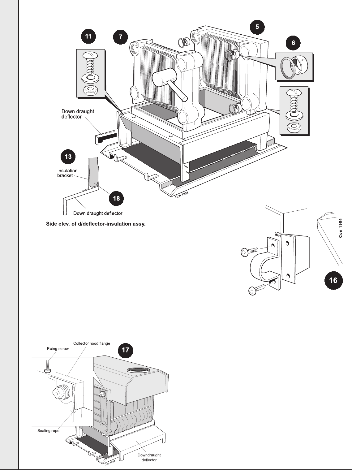
12.Offer the downdraught deflector to the projecting studs at the
back of the combustion chamber and fix, using the nuts and
washers provided.
13.Fit the insulation brackets with the screws provided to the
downdraught deflector.
14.Refit the burner assembly to the combustion chamber and
tighten the 4 nuts securing the burner manifold to the
combustion chamber legs. Offer up the burner light back
shield to the combustion chamber - with the cutout for the
flame detector electrode at the LH end - and fasten, using
the M5 nuts and washers.
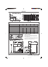
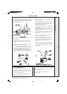
15.Fit the gas valve and spark generator assembly to the boiler
by doing up the union in the gas line and by fastening the
spark generator bracket to the combustion chamber
using the two M5 screws and washers.
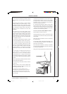
16.Fit the gas inlet pipe and retain by the semi-circular
clamp, screws and washers provided. Tighten both
unions and the inlet pipe retaining clamp, ensuring
that the gas valve assembly is vertical.
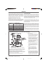
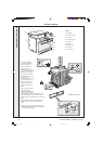
17.To fit the collector hood align the back edge of the
horizontal side returns with the rear of the section
assembly and fasten down the collector hood (using
the M6 screws and nuts provided) through the side
fixing points.
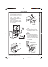
18.Wrap the insulation around the heat exchanger with
the foil outside, tuck behind the insulation brackets
on the downdraught deflector and fasten at the edge,
using the foil tabs and tape provided.
19. Fit the NOx ducts into the burner aeration intakes
and fasten to the collector hood, using the M5
elongated nuts.
Note.
The insulation MUST be behind the NOx ducts (it will be
compressed behind the ducts.)
INSTALLATION
157294-3.pmd 11/8/2005, 9:58 AM12