


INSTALLATION
13
Concord CXSi/H - Installation & Servicing
8
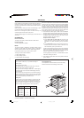
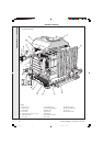
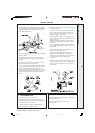
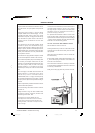
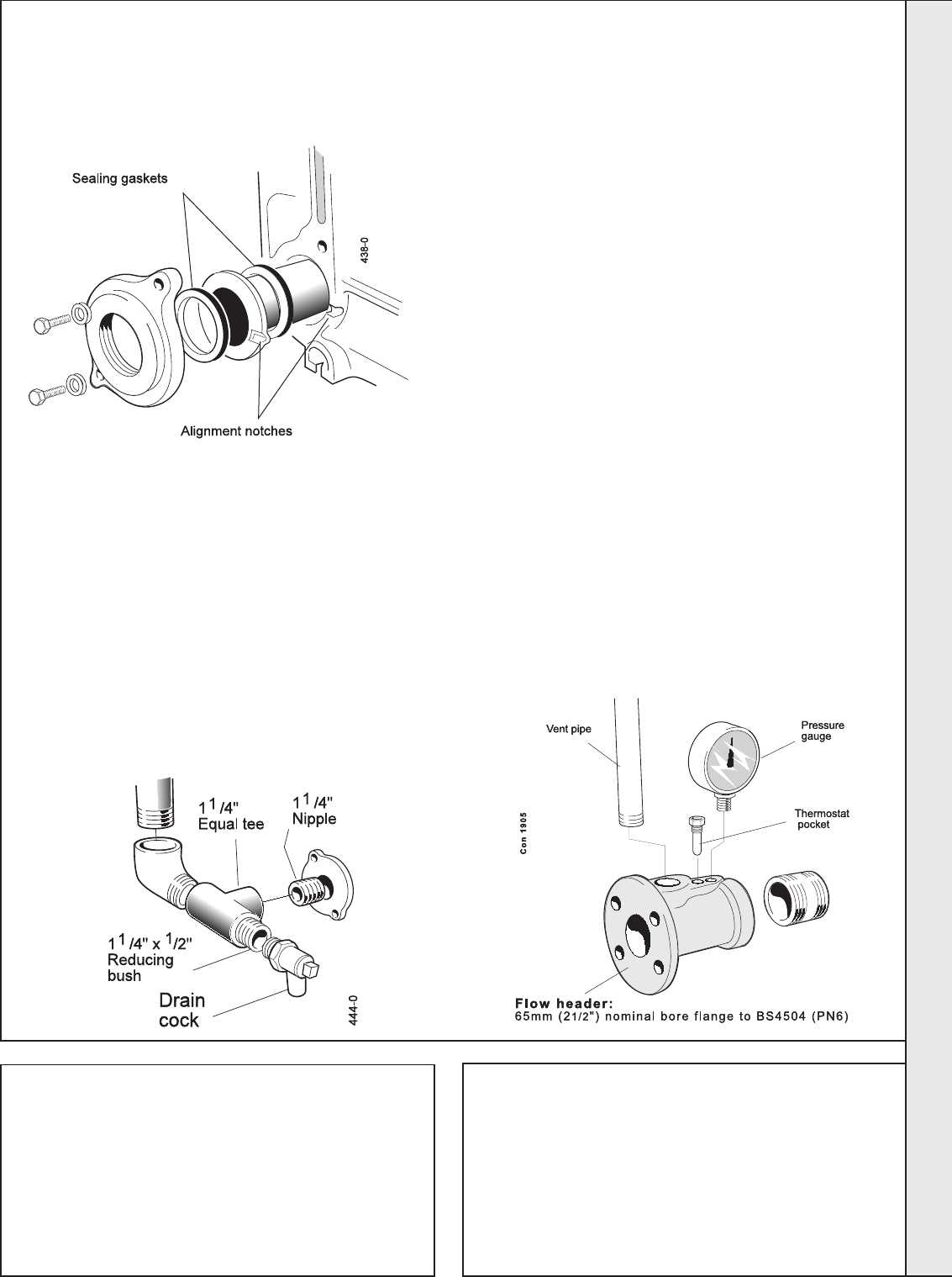
BOILER ASSEMBLY
1. Fit the distributor tube into the selected return connection.
Ensure that the tube flange aligns horizontally and that the
2 sealing gaskets are correctly assembled on the tube -
refer to alignment notches.
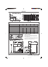
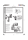
1. Complete the secondary flue connection.
The boiler is designed to accept flues to BS.835. If a
suitable adaptor is used then flues to BS715 may be fitted.
2. Seal with an approved boiler putty.
3. A split socket should be fitted immediately above the
boiler to facilitate disconnection of the flue.
9
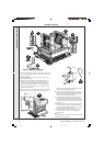
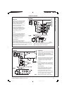
FLUE CONNECTION
Connect the gas supply to the gas inlet pipe - Table 2 gives
details of the inlet pipe size.
The use of an approved gas cock and union is
recommended here.
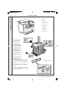
Fit the 2" tapped flange, using the M10 x 35mm screws and
washers provided.
2. Fit the blank flange to the other lower rear connection,
using the gasket and M10 x 25mm screws and washers
provided.
3. Fit the blank flange to the RH front connection, using the
gasket and M10 x 25mm screws provided.
4. The 1
1/4" tapped flange and gasket should be fitted to the
LH front connection with the reducing bush and 1/2" drain
cock. If the cold feed/expansion pipe is to be brought
directly to the boiler, the close taper nipple and 1 1/4" tee
must be fitted so that the drain cock is horizontal. This will
reduce the possibility of the drain becoming blocked by
debris.
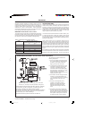
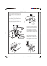
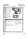
5. Complete the system connections (using suitable jointing
compound) as follows:
The cast iron flow header must be fitted in the chosen
flow connection which will be either of the 2 top rear
tappings. A length of 2" BSP pipe is contained in the
Plateware Package for this purpose.
Fit the flow header so that the 1 1/2" vent tapping in the
header is vertical. Screw the thermostat pocket into one
of the 1/2" tappings.
The other 1/2" tapping is used for the pressure gauge
provided. The flow header terminates in a 2 1/2" flange
connection.
The 1 1/2" BSP tapping on the top of the flow header is
for a vent pipe ONLY and MUST NOT be used for any
other purpose.
A safety valve may be fitted in the remaining top rear
tapping, in accordance with CP332:3.
The unused top rear tapping may be used as an
alternative and independent open vent / safety pipe
connection. The LH front bottom tappings may be used
for an independent cold feed / expansion pipe
connection.
In order to avoid air locks, reduction in pipe sizes should
be made in the vertical plane or eccentric bushes used.
Finally , plug the unused tappings, using the 2" BSP
plugs supplied.
10
GAS CONNECTION
INSTALLATION
157294-3.pmd 11/8/2005, 9:58 AM13