


© 2004 Hunter Fan Company 41810-01 08/20/2004
9
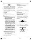
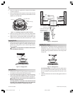
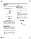
Figure 27 - Receiver jumper switches
installing the light fixture
You can install with or without the light fixture. If you want to
install without the light fixture, skip to the installing without the
light fixture section.
WARNING: Use only the supplied light fixture for this fan
model.
attaching the upper switch housing
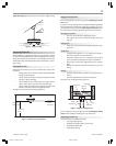
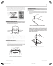
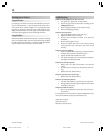
1. Partially install two #6-32 x 3/8" housing assembly screws into
the switch housing mounting plate as shown in Figure 28.
2. Feed the upper plug connector through the center opening of
the upper switch housing. See Figure 28.
Figure 28 - Attaching the upper
switch housing to the mounting plate
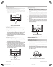
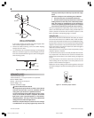
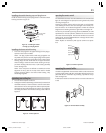
3. Align the keyhole slots in the upper switch housing with the
housing assembly screws installed previously.
4. Turn the upper switch housing counterclockwise until the
housing assembly screws are firmly situated in the narrow end
of the keyhole slots as shown in Figure 29. Install the one re-
maining #6-32 x 3/8" housing assembly screw into the third
hole in the upper switch housing. Tighten all three screws
firmly.
Figure 29 - Mounting the upper switch housing
CAUTION: Make sure the upper switch housing is se-
curely attached to the switch housing mounting plate. Fail-
ure to properly attach and tighten all three housing assem-
bly screws could result in the switch housing and light fix-
ture falling.
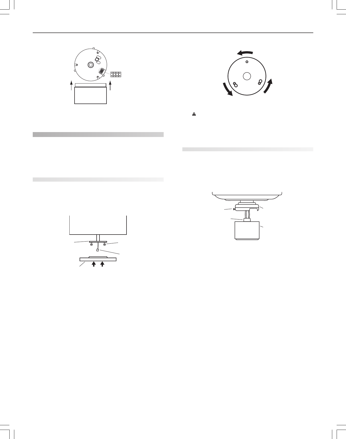
attaching the lower switch housing
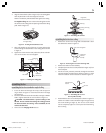
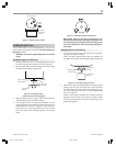
1. First insert the plug from the upper housing into the plug re-
ceptacle in the receiver module.
NOTE: The plug is polarized and will only go together one
way. Make sure you have correctly aligned plug and receptacle.
Figure 30 - Connecting the plug connectors
2. Place the lower switch housing assembly over the upper switch
housing. Align the side screw holes in the upper and lower
switch housings. Attach the lower switch housing to the up-
per switch housing with three #6-32 x 3/8" housing assembly
screws. See Figure 30.
NOTE: If the two pieces are difficult to assemble, check the
alignment of the (3) slots in the top of the receiver module
and the mounting holes in the lower switch housing. They
should align together.
Receiver Bottom
Jumper
Switch
Lower Switch Housing
Pull receiver
out of switch
housing
Switch Housing
Mounting Plate
Upper Switch
Housing
Housing
Assembly
Screw
Upper Plug
Connector
Assembly Screw
Plug Connector
Upper Switch
Housing
Lower Switch
Housing
41810-01_rev 8-20-04 v 3.pmd 8/21/04, 4:36 PM9