


41810-01 08/20/2004 © 2004 Hunter Fan Company
8
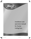
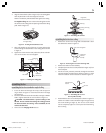
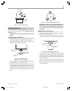
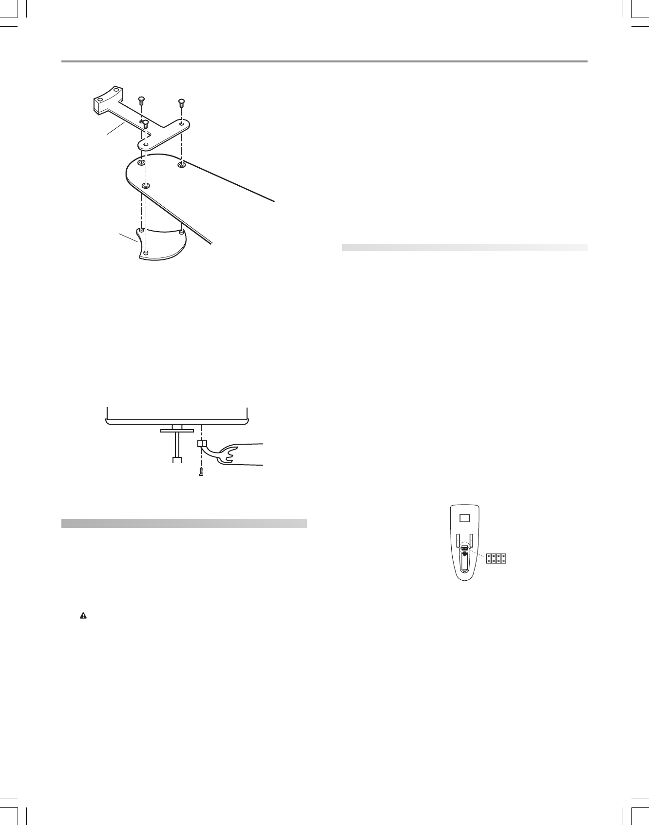
Figure 24 - Attaching the blade
to the blade iron and medallion
If you used grommets, the blades may appear slightly loose
after screws are tightened. This is normal.
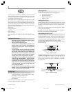
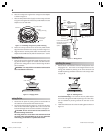
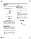
3. Remove the blade mounting screws and rubber shipping
bumpers from the motor.
4. For each blade, insert one blade mounting screw through the
blade iron as shown in Figure 25, and attach lightly to the fan.
Insert the second blade mounting screw, then securely tighten
both mounting screws.
Figure 25 - Attaching the blade iron to the fan
setting up the remote
Transmitter Model: 85095
Transmitter Battery: 12 V, Type 23A, MN-21 or equivalent
Receiver Model: 85069
Ratings: 120 VAC, 60 Hz,1.0 Amp Fan
Receiver Weight: 8 oz.
240 Watts incandescent light
Caution: Risk of Electrical Shock!
All wiring must be performed in accordance with national
and local electrical codes. If you are unfamiliar with the
wiring codes, you should use a qualified electrician.
To avoid overheating and possible damage to other equip-
ment, do not install to control a receptacle, fluorescent
light fixture, motor operated appliance, or transformer-
supplied appliance. Use only to control one paddle-blade
ceiling fan and incandescent light fixture.
This device complies with part 15 of the FCC rules. Changes
or modifications not expressly approved by Hunter Fan
Company could void your authority to operate this equip-
ment!
Operation Is Subject To The Following Two Conditions:
1. This device may not cause harmful interference.
2. This device must accept any interference received, in-
cluding interference that may cause undesired operation.
Note: Any changes or modifications to the transmitter or
receiver not expressly approved by Hunter Fan Company
may void one’s authority to operate this remote control.
Your fan is equipped to be operated by remote control. A receiver
device is mounted inside the fan switch housing. A hand-held trans-
mitter is packed in the fan box. The transmitter requires a 12-volt
battery (included). The operating range is 15-30 feet.
setting the code
When two or more fans are located near each other, you may de-
sire to have each of them set to a different code, so that the opera-
tion of one fan will not affect another. This is accomplished by chang-
ing the position of any one or more of a group of 3 jumpers grouped
together in the transmitter. The receiver located in the switch hous-
ing has the same set of 3 jumpers which must also be changed to
match the transmitter settings.
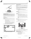
These jumpers are very small and can best be operated by using a
small pair of pliers or tweezers.
In the transmitter, the jumpers are readily accessible from the bat-
tery compartment. The switches in the receiver are located at the
bottom of the receiver device in the switch housing. See Figures 26
and 27.
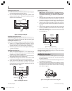
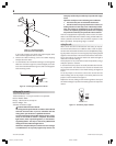
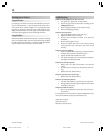
To set the jumpers in the receiver, remove the receiver from the
switch housing and set the jumpers in the same positions as the
jumpers in the transmitter. See Figure 27.
Replace the receiver, making sure the mounting holes at the top of
the switch housing line up with the matching slots in the top of the
receiver.
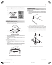
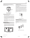
Figure 26 - Transmitter jumper switches
Blade Iron
Medallion
Jumper
Switch
Transmitter Back
41810-01_rev 8-20-04 v 3.pmd 8/21/04, 4:36 PM8