EXCEL 10 FCU CONTROLLER LNS PLUG-INS USER GUIDE
EN2B-0285GE51 R0909
26
Output
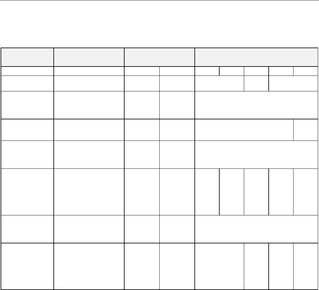
The available options for output configurations with the default values shown are listed in Table 16. See section "Configurations"
on page 12 for more information about parameters.
Table 16. FCU Controller output configuration options and default configurations
function configuration options
default configuration
W7752
default configuration
W7754
model D,F E,G,J K
4
L M N P
system type
2-pipe (1 valve)
4-pipe (2 valves)
4-pipe 4-pipe 4-pipe 2-pipe 4-pipe
fan type
no fan
1-speed fan
2-speed fan
3-speed fan
3-speed 3-speed 3-speed
relay 4
(reheat relay)
reheat
network control (free use)
not used
reheat not used not used reheat
output 1
(triac 1 and 2)
3
control
1
not used
cooling
heating
heat/cool changeover
heating heating heating
output 1
(triac 1 and 2)
3
type
floating
floating-mid
2
1-stage
2-stage
3-stage
PWM
thermal
floating floating PWM
ther-
mal
floating
ther-
mal
floating
output 2
(triac 3 and 4)
3
control
1
not used
cooling
heating
heat/cool changeover
cooling cooling cooling
output 2
(triac 3 and 4)
3
type
floating
floating-mid
2
1-stage
2-stage
3-stage
PWM
thermal
floating floating thermal floating
ther-
mal
floating
Notes:
1. The output mode settings apply only to a 4-pipe system. In a 2-pipe system, output 1 will always operate in the changeover
mode.
2. The floating-mid option is for changeover applications, only, and uses only one of the two outputs.
3. The operation of the triacs based upon the output type is given in Table 12 on page 21 and in Table 14 on page 23.
4. W7754K1001 is equipped with a low-voltage digital output suitable for connection to a solid-state relay employed for low-
voltage PWM control in high-current electric reheat applications; this digital output is activated if output 1 type is set to either
"PWM" or "thermal".


