EXCEL 10 FCU CONTROLLER LNS PLUG-INS USER GUIDE
EN2B-0285GE51 R0909
17
APPLICATION STEPS
Overview
Steps one through seven (see Table 8) address con-
siderations for engineering an Excel 10 FCU System. These
steps are guidelines intended to aid understanding of the pro-
duct I/O options, bus arrangement choices, configuration
options and the Excel 10 FCU Controllers’ role in the overall
EXCEL 5000
®
System architecture.
Table 8. Application steps
Step No. Description
1 Plan the System
2 Determine Other Bus Devices Required
3 Lay Out Communication and Power Wiring
4 Prepare Wiring Diagrams
5 Order Equipment
6 Configure Controllers
7 Troubleshooting
Step 1. Plan the System
Plan the use of the FCU Controllers according to the job
requirements. Determine the location, functionality and sensor
or actuator usage. Verify the sales estimate of the number of
FCU Controllers and wall modules required for each model
type. Also check the number and type of output actuators and
other accessories required.
When planning the system layout, consider potential ex-
pansion possibilities to allow for future growth. Planning is
very important to be prepared for adding HVAC systems and
controllers in future projects.
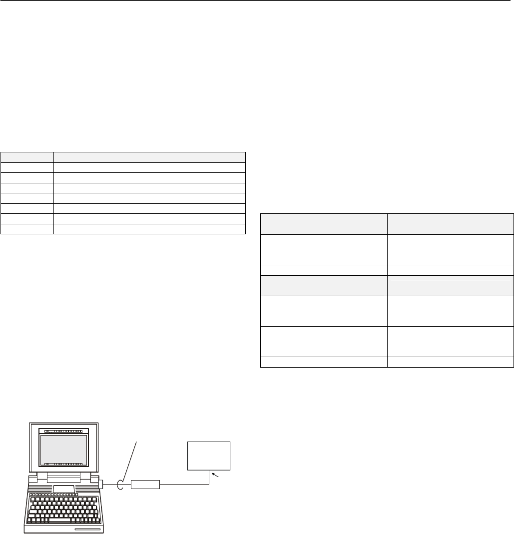
notebook PC
using an LNS tool
SLTA
Excel 10
FCU
controller
shielded
interface
cable
RS-232
serial
port
LonWorks
port
Fig. 12. Connecting the portable operator terminal to the
L
ONWORKS network
The L
ONWORKS communication loop between controllers must
be laid out according to the guidelines applicable for that
topology. FCU Controllers use FTT technology which allows
daisy chain, star, loop or combinations of these bus
configurations. See section "Step 3. Lay Out Communications
and Power Wiring" (page 18) for more information on bus
wiring layout, and see Fig. 13, Fig. 14, and Fig. 15 in section
"Step 4. Prepare Wiring Diagrams" (page 19) for wiring
details.
It is important to understand the interrelationships between
FCU Controllers on the L
ONWORKS network early in the job
engineering process to ensure their implementation when
configuring the controllers. (See section "Step 6. Configure
Controllers" [page 25] for information on the various Excel 10
FCU Controller parameters and on Excel 10 FCU Controller
point mapping.)
Step 2. Determine Other Bus Devices
Required
A max. of 62 nodes can communicate on a single LONWORKS
segment. If more nodes are required, a router is necessary.
Using a router allows up to 125 nodes, divided between two
L
ONWORKS segments. The router accounts for two of these
nodes (one node on each side of the router). Table 9
summarizes the L
ONWORKS segment configuration rules.
Table 9. LonWorks configuration rules and number of
device nodes
One LONWORKS Segment
(Example)
Max. No. of Nodes = 62
Max. no. of Excel 10
Controllers
60 nodes (T7460/T7560 wall
modules are not L
ONWORKS
nodes)
Total 62 nodes
Two LONWORKS Segments
(Example)
Max. No. of Nodes = 125
Max. no. of Excel 10
Controllers in segment
number one
60 nodes (T7460/T7560 wall
modules are not L
ONWORKS
nodes)
Max. no. of Excel 10
Controllers in segment
number two
60 nodes (T7460/T7560 wall
modules are not L
ONWORKS
nodes)
Total 125 nodes
The max. length of an FTT L
ONWORKS segment is 4600 ft
(1400 m) for a daisy chain configuration or 1650 ft (500 m)
total wire length and (400 m) node-to-node for any other type
of configuration.
NOTE: In the case of FTT L
ONWORKS segments, the
distance from each transceiver to all other trans-
ceivers and to the termination must not exceed the
max. node-to-node distance. If multiple paths exist,
the longest one should be used for the calculation.
If longer runs are required, add a router in order to partition
the system into two segments.
In addition, all L
ONWORKS segments require the installation of
a Bus Termination Module. For an FTT L
ONWORKS segment,
one or two Termination Modules may be required depending
upon the bus configuration. See section "Step 3. Lay Out
Communications and Power Wiring" (page 18) and the
L
ONWORKS Termination Module subsection in section "Step 4.
Prepare Wiring Diagrams" (page 19) for more details.
