


MV100 ELECTRIC CONTROLLERS T100, T200 THERMOSTATIC CONTROLLERS AND V2000 RADIATOR VALVES
9 62-3048—2
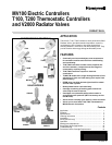
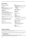
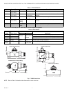
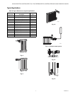
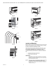
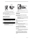
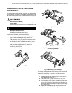
Fig. 21. Horizontal-body V2000 application.
Install controllers with external sensors in any position. The
sensor can easily be mounted in a position to measure and
control the room air temperature.
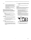
NOTE: When temperature of medium exceeds 190°F (88°C),
mount the MV100 horizontally.
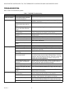
WIRING (MV100 ONLY)
Wire the MV100 according to Fig. 18.
CAUTION
Equipment Damage Hazard.
Can short equipment circuitry.
Disconnect all power supplies before installation.
CAUTION
Equipment Damage Hazard.
Connecting improper voltage can damage the
device beyond repair.
Connect only 24 Vac or 24 Vdc to the MV100.
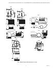
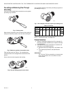
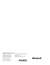
Fig. 22. MV100 internal schematic and wiring connections.
OPERATION
The T100 and MV100 Controllers contain temperature-
sensitive capsules that expand or contract in reaction to
temperature changes.
— When the capsule expands, pressure from the expand-
ing material closes the valve, preventing flow through
the radiation unit.
— When the capsule contracts, the valve opens and flow
resumes through the radiation unit.
T100
The T100 temperature-sensitive capsule expands when the
temperature rises above the setpoint.
MV100
When signalled by the thermostat, an electric element in the
MV100 heats the capsule causing it to expand.
NOTE: For normally open MV100 models, the capsule cools
when signalled by the thermostat.
SETTINGS AND ADJUSTMENTS
When installation is complete, rotate the setpoint dial to the
desired setting.
NOTE: The setpoint varies with the location of the sensor. A
floor level sensor controls at a setpoint different from
the wall level sensor.
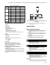
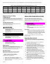
Normally, correction of an overheating or underheating
condition requires only small changes. See Table 5 for dial
markings and corresponding temperature settings. After
changing the setting, allow the valve at least 30 minutes to
stabilize.
INCORRECT
CORRECT
M16272A
L1
(HOT)
L2
PTC
RESISTANCE
HEATER
YELLOW
T810/T822
YELLOW
1
1
2
3
POWER SUPPLY. PROVIDE DISCONNECT MEANS AND OVERLOAD
PROTECTION AS REQUIRED.
NORMALLY OPEN END SWITCH CLOSES WHEN MV100 IS POWERED.
SUGGESTED HEAT ANTICIPATOR SETTING IS 0.35A.
3
2
RED
END
SWITCH
RED
TO CIRCULATOR
PUMP MULTIZONE
PANEL OR BURNER
RELAY
MV100
M12947
A