


MV100 ELECTRIC CONTROLLERS T100, T200 THERMOSTATIC CONTROLLERS AND V2000 RADIATOR VALVES
62-3048—2 4
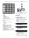
Table 1. T100,T200 Models.
a
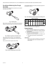
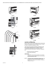
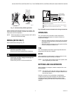
Mount the unit horizontally on the valve body for accurate temperature regulation.
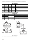
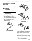
Table 2. V2000 Models.
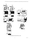
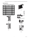
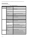
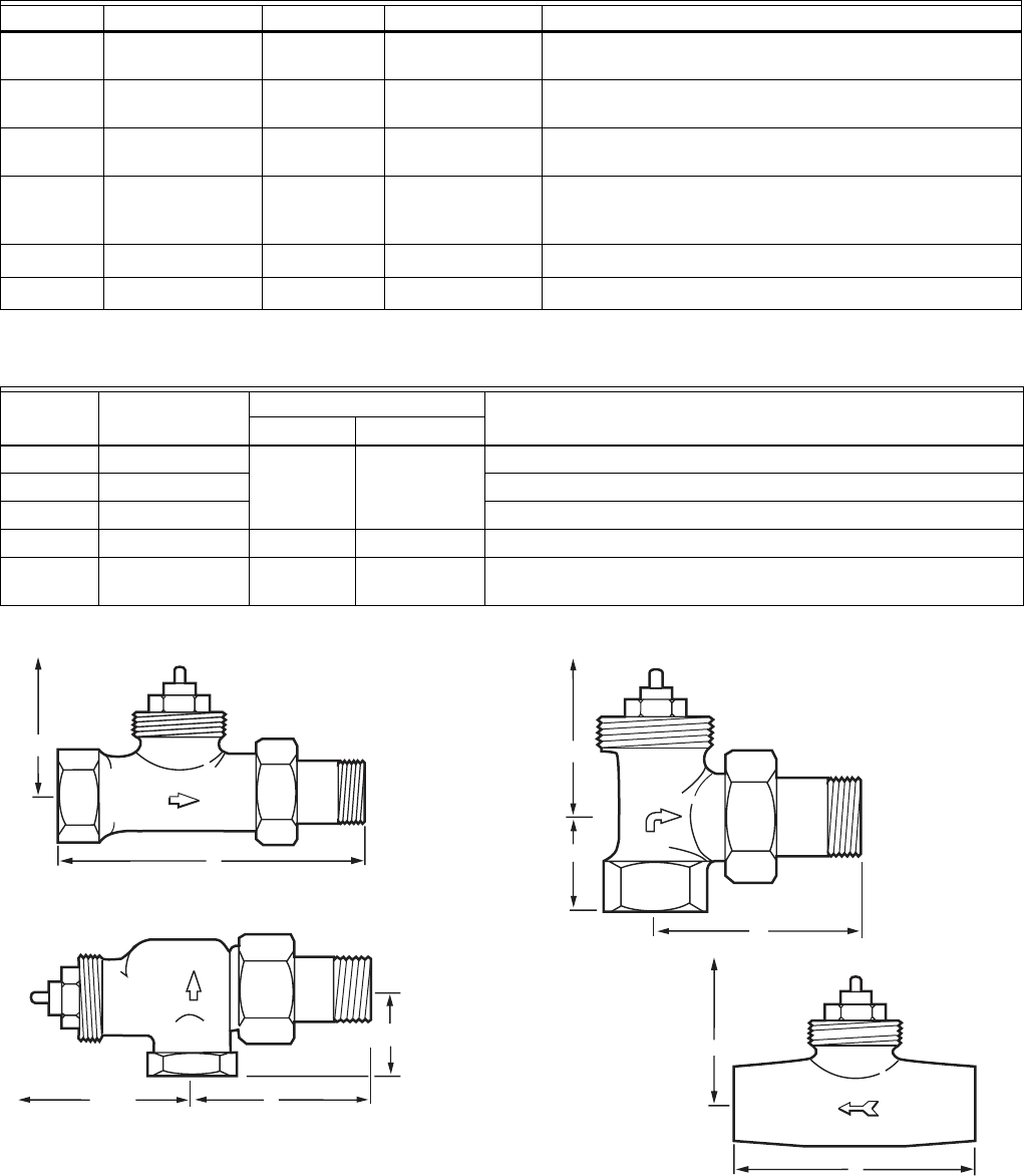
Fig. 2. V2000 dimensions.
NOTE: Refer to Table 3 for detailed valve dimensions for each valve size.
Model Control Range Mounting Capillary Description
T100A 43°F to 79°F
(6°C to 26°C)
Direct
a
None Components are in one unit.
T100B 48°F to 79°F
(9°C to 26°C)
Remote One 6-1/2 ft (2 m)
or 16 ft (5 m)
Sensor and setpoint dial combined and remote from valve
actuator.
T100C Remote Two 4-1/2 ft
(1.4 m)
Components mount remotely from each other.
T100F 43°F to 79°F
(6°C to 26°C)
Direct with
remote
sensor.
One 6-1/2 ft (2 m) Sensor is remote from combination setpoint dial and valve
actuator.
T100M
Direct
a
None Components are in one tamper-resistant unit.
T200A
Direct
a
None White body with chrome-plated end.
Model Body Pattern
Connection
ApplicationInlet Outlet
V2040D Straight NPT
Threaded
Union Nut with
NPT Threaded
or Sweat
Use where manual valves were not originally installed.
V2040E Angle Typically used with remote temperature sensing controllers.
V2040A Horizontal Angle Typically used with direct-mount controllers (T100A,M; T200A)
V200LD Straight Sweat Sweat Use with copper tubing installations.
V2042H/
V2043H
One-Pipe 18 in. NPT 1/8 in NPT for
SA123A Vent
Use in single-pipe steam applications.
A
M12930B
B MAX.
V2040D (Straight Body)
A
M12932B
C
B MAX.
V2040A (Horizontal Angle Body)
A
M12933B
B MAX.
V200LD (Straight Body)
A
M12931B
C
B MAX.
V2040E (Angle Body)