


MV100 ELECTRIC CONTROLLERS T100, T200 THERMOSTATIC CONTROLLERS AND V2000 RADIATOR VALVES
5 62-3048—2
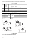
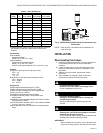
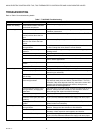
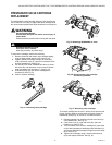
Table 3. Valve Dimensions.
a
B Max dimension is with T100A control installed, except for
the V2042H, for which it is without the steam/air vent
installed.
Connections:
Inlets Available:
Internally threaded.
Sweat (1/2 in. and 3/4 in. only).
Outlets Available:
Union nut with threaded tailpiece.
Sweat (1/2 in. and 3/4 in. only).
Union nut with sweat tailpiece (1/2 in. and 3/4 in. only).
Capacity:
Cv (gpm at 1 psi drop across fully-open valve):
1/2 in.: 2.0.
3/4 in.: 2.2.
1 in.: 2.3.
Btuh (Btu/hr at 7 psi drop across fully-open valve):
1/2 in.: 59,100.
3/4 in.: 63,800.
1 in.: 70,500.
Accessories:
203225 Replacement Bulb Guard for T100F.
272844 Locking Cap and Limit Pins for T100M.
272873 MT100C Cartridge Tool Driver Upgrade Kit.
A104F Limit Pins for T100A,F.
VS1200SL01 Replacement Valve Cartridge.
G111B Bulb Guard to protect T100C sensor when
wall-mounted.
VA8200A001 Valve Cartridge Replacement Tool for system
under pressure (V2000).
Q110D Inlet Strainer Inserts for NPT V100 (models available
for 1/2 in. and 3/4 in. valves).
SA123A Steam/Air Vent for V2042HSL10 One-pipe Steam
Valve.
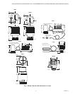
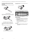
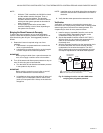
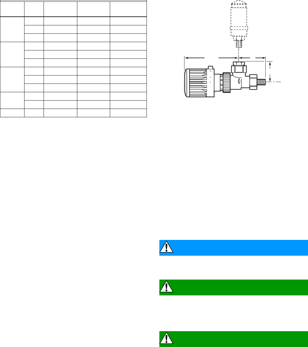
Fig. 3. V2042H (Body)/V2043H (Body with Airstream Vent)
Dimensions.
NOTE: Refer to Table 3 for detailed valve dimensions for
each valve size.
INSTALLATION
When Installing this Product...
1. Read these instructions carefully. Failure to follow them
could damage the product or cause a hazardous
condition.
2. Check the ratings given in the instructions and on the
product to make sure the product is suitable for your
application.
3. Installer must be a trained, experienced service
technician.
4. After installation is complete, check out product
operation as provided in these instructions.
CAUTION
Equipment Damage Hazard.
Excessive force can distort and damage valve.
Do not overtighten the union nut.
CAUTION
Equipment Damage Hazard.
Driving an unmounted MV100 can damage the
actuator beyond repair.
Mount the MV100 before applying power to the
actuator.
CAUTION
Sweat Valve Damage Hazard.
Soldering the valve with the cartridge or controller
attached can damage the device.
Prior to attaching valve to piping, remove controller and
cartridge from potential exposure to heat.
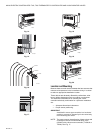
IMPORTANT
When installing the valve body, ensure that the arrow
(cast into the body) points in the direction of the flow.
Valve
Size in
in.
A
in in. (mm)
B Max
a
in in. (mm)
C
in in. (mm)
V2040D 1/2 3-3/4 (95) 4-1/16 (104) —
3/4 4-3/16 (106) 4-1/16 (104) —
1 4-1/2 (114) 4-1/2 (114) —
V2040E 1/2 2-5/16 (58) 3-3/16 (98) 1 (26)
3/4 2-5/8 (66) 3-13/16 (98) 1-1/8 (29)
1 2-15/16 (74) 4-5/16 (110) 1-5/16 (34)
V2040A 1/2 2-1/8 (54) 4-1/2 (115) 1-1/8 (28)
3/4 2-1/2 (64) 5-3/16 (132) 1-3/16 (31)
1 2-15/16 (74) 5-3/16 (132) 1-7/16 (37)
V200LD 1/2 2-5/8 (66) 4-1/16 (104) —
3/4 2-15/16 (74) 4-1/16 (104) —
V2042H 3/8 1-11/16 (43) 3-13/16 (98) 1-3/16 (31)
M17016
5
6 0
B MAX. A
C