


MV100 ELECTRIC CONTROLLERS T100, T200 THERMOSTATIC CONTROLLERS AND V2000 RADIATOR VALVES
62-3048—2 10
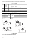
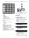
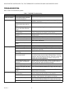
Table 6. T100 and T200 Settings and Corresponding Temperatures in °F (°C).
a
Setting not marked on dial.
Setpoint Locking or Limiting
(T100A,F,M only)
A single temperature or range-limiting lock is available for the
T100A,F,M. See Accessories in the Specifications section.
Refer to the T100A,F,M Installation Instructions for procedural
details.
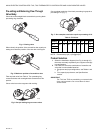
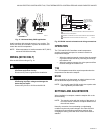
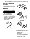
Cartridge Replacement
With the appropriate tools, the V2000 cartridge can be
replaced while under pressure.
WARNING
Severe Scalding Hazard.
Contact with hot liquid can lead to severe injury
or cause death.
For a pressurized valve, only open with Valve Cartridge
Replacement Tool.
CAUTION
Hot Surface Hazard.
Contact with hot valve body can cause
severe burning.
Service cartridge only when valve body is cool.
CAUTION
Hazardous Splashing Fluids.
Can injure, burn, or blind.
Wear safety glasses or goggles.
Under Pressure
Replacing the V100 Cartridge with the system under pressure
requires the Valve Cartridge Replacement Tool (see
Accessories in the Specifications section). See Pressurized
Valve Cartridge Replacement section for details.
Not Under Pressure
Replacing the cartridge without the Valve Cartridge
Replacement Tool requires one of the following:
• Isolation of valve from system pressure.
• System shutdown and drain to valve level.
Once the valve is not pressurized:
1. Using a 3/4 in. (19 mm) hex (6- or 12-point) socket
wrench, remove and discard the cartridge.
2. Clean the inside of valve and cartridge sealing surfaces.
Install a new cartridge.
NOTE: Torque cartridge to 25 ft-lb.
SINGLE-PIPE STEAM APPLICATIONS
Many older buildings original heating systems were
single-pipe steam. The advantage of single-pipe steam
systems is lower initial cost, resulting from the use of less
piping and elimination of radiator steam traps.
CAUTION
Boiler Flooding Hazard.
Loss of system control and boiler damage can
result.
For a one-pipe steam system radiator, install valve only
at the vent location.
IMPORTANT
Ensure vacuum breakers are installed on the steam
system risers. If vacuum breakers (that open to the
atmosphere at zero psig) are not installed, the system
can develop a negative pressure and pull steam back
into the radiators on resumption of steam.
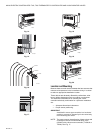
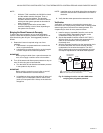
Refer to Fig. 12 for installing the one-pipe steam radiator
adapter assembly.
Single-Pipe Steam Systems
T100/V2043H (with vent) operation to provide temperature
control for a formerly uncontrolled single-pipe steam system
follows:
1. The boiler is off (zero steam pressure); radiators are
filled with air; the vent is open.
2. The T100 calls for heat, opening the valve.
3. At the command of an external controller (such as a
representative zone thermostat, or a timer controlled by
outside temperature) the boiler cycles on and begins
delivering steam to the system.
4. Steam enters the radiator, forcing air through the open
V2042H and out through the vent.
5. Once the air is exhausted, the steam heats the
thermostatic element of the vent, causing it to close.
6. The steam cools forming condensation. Condensation
flows out of the radiator making room for more steam to
enter.
7. The T100 is eventually satisfied (temperature equals the
setpoint) and it closes the V2042H.
8. The air in the system (introduced by the vacuum
breakers) begins to fill the radiator. The air in the radiator
prevents steam from coming in and the radiator cools.
9. The boiler cycles off by command of components
external to the T100/V2042H and the steam pressure
returns to zero.
0*123456
T100A,F 32 (0) 43 (6) 46 (8) 54 (12) 61 (16) 68 (20) 73 (23) 79 (26)
T100B,C — 55 (13) 61 (16) 64 (18) 68 (20) 72 (22) 75 (24)
79 (26)
a
T100M — 43 (6) 61 (16) 64 (18) 68 (20) 72 (22)
75 (24)
a
79 (26)
a
T200 — 43 (6) 52 (11) 57 (14) 63 (17) 68 (20) 73 (23) 79 (26)