


MV100 ELECTRIC CONTROLLERS T100, T200 THERMOSTATIC CONTROLLERS AND V2000 RADIATOR VALVES
62-3048—2 6
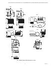
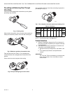
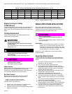
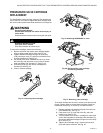
Pre-setting and Balancing Flow Through
Valve Body.
Close valve with straight blade screwdriver by turning black
pre-setting ring clockwise.
Fig. 4. Closing valve.
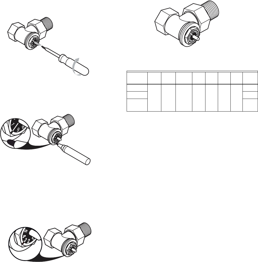
When closed, the position of the screwdriver slot equals pre-
setting zero. Mark the position of the slot with a felt tip pen.
Fig. 5. Mark zero position of screwdriver slot.
Take required value from Table 4. Turn presetting ring
counterclockwise with a straight blade screwdriver to this
position.
Chose value has to be congruent with marking.
Fig. 6. Set pre-setting ring to correct value.
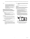
One complete revolution of the black pre-setting ring equals a
pre-setting of 10 (Fig. 7).
Fig. 7. One complete revolution equals a pre-setting of 10.
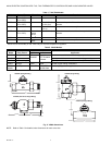
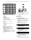
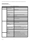
Table 4. CV Values.
NOTE: Pressure drop (psi) = (flow[gpm]/cv)
2
.
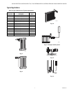
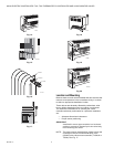
Product Selection
1. Select the installation diagram (from Fig. 4 through 16)
that most accurately represents your equipment and pip-
ing configuration.
2. Use Table 4 to select the combination of controller and
valve that is most suitable based on:
a. Equipment and pipe configuration, see Tables 1 and
2.
b. Flow capacity requirement, see Specifications
section.
IMPORTANT
The T100 and T200 are modulating, not manual shut-
down, valve actuators. Do not use them for hand
shutoff valves.
M22687
M22688
M22689
Pre-
setting 1 2 3 4 5 6 7 Open
3/8 in. 0.29 0.58 0.87 1.16 1.45 1.68 1.80 2.00
1/2 in. 2.15
3/4 in.,
1 in.
2.26
M22690