


RM7800E,G,L,M; RM7840E,G,L,M 7800 SERIES RELAY MODULES
66-1085—3 6
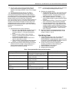
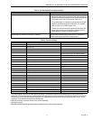
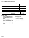
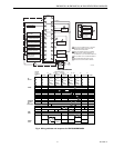
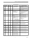
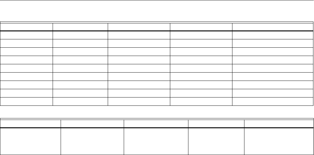
Table 4. Combinations for Terminals 8, 9, 10 and 21.
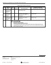
Table 5. Explanation of Each Combination.
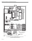
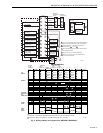
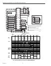
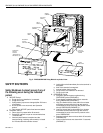
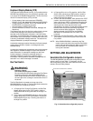
Mounting RM7800/RM7840
Relay Module (Fig. 5)
1. Mount the RM7800/RM7840 vertically on the Q7800
Subbase, or mount horizontally with the knife blade
terminals pointing downward. When mounted on the
Q7800A, the RM7800/RM7840 must be in an electrical
enclosure.
2. When mounting in an electrical enclosure, provide
adequate clearance for servicing, installation and
removal of the RM7800/RM7840, Keyboard Display
Module, flame amplifier, flame amplifier signal voltage
probes, electrical signal voltage probes, and electrical
connections.
a. Allow an additional two inches below the
RM7800/RM7840 for the flame amplifier mounting.
b. Allow an optional three-inch minimum to both sides
of the RM7800/RM7840 for electrical signal voltage
probes.
3. Make sure no subbase wiring is projecting beyond the
terminal blocks. Tuck in wiring against the back of the
subbase so it does not interfere with the knife blade
terminals or bifurcated contacts.
IMPORTANT
The RM7800/RM7840 must be installed with a
plug-in motion rather than a hinge action.
4. Mount the RM7800/RM7840 by aligning the four
L-shaped corner guides and knife blade terminals with
the bifurcated contacts on the wiring subbase and
securely tighten the two screws without deforming the
plastic.
Combination No. Pilot Fuel 8 Main 9 Ignition 10 Intermittent Pilot Valve 21
1 C F No Load No Load
2 B F No Load No Load
3 No Load F No Load B
4F F A No Load
5 No Load F A F
6D F A No Load
7 No Load D A D
8D D A No Load
9 No Load D A D
AB CD F
4.5A ignition. 50 VA Pilot Duty plus
4.5A ignition.
180 VA ignition plus
motor valve with:
660 VA inrush, 360 VA
open, 260 VA hold.
2A Pilot Duty. 64 VA Pilot Duty plus motor
valves with:
3850 VA inrush, 700 VA
open, 250 VA hold.