


RM7800E,G,L,M; RM7840E,G,L,M 7800 SERIES RELAY MODULES
3 66-1085—3
4. All wiring must comply with all applicable electrical
codes, ordinances and regulations. Wiring, where
required, must comply with NEC, Class 1 (Line Voltage)
wiring.
5.
Recommended wire size and type: see Table 1.
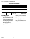
6. Recommended grounding practices: see Table 2.
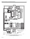
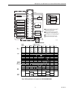
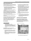
The Keyboard Display Module, Data ControlBus Module™
(for remote mounting or communications), through a 203541
5-wire Connector, or Communication Interface ControlBus
Module must be wired in a daisy chain configuration,
(1(a)-1(a), 2(b)-2(b), 3(c)-3(c)). The order of interconnection of
all the devices listed above is not important. Be aware that
modules on the closest and farthest end of the daisy chain
configuration string require a 120 ohm (1/4 watt minimum)
resistor termination across terminals 1 and 2 of the electrical
connectors, for connections over
100 feet.
7. Recommended wire routing of leadwires:
a. Do not run high voltage ignition transformer wires in
the same conduit with the flame detector, Data
Controlbus Module™, or Remote Reset Module
wiring.
b. Do not route flame detector, Data Controlbus
Module™, or Remote Reset Module leadwires in
conduit with line voltage circuits.
c. Enclose flame detector leadwires without armor
cable in metal cable or conduit.
d. Follow directions in flame detector, Data Controlbus
Module™, or Remote Reset Module Instructions.
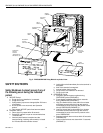
8. Keyboard Display Module (KDM): Because the KDM is
powered from a low voltage, energy limited source, it
can be mounted outside of a control panel if it is
protected from mechanical damage.
NOTE: A 13 Vdc power supply must be used any time more
than one Keyboard Display Module is used.
9. Maximum wire lengths follow:
a. RM7800/RM7840 leadwires—The maximum length
of leadwire is 300 feet to terminal inputs (Control,
Preignition Interlock, Running/Lockout Interlock,
High Fire Switch and Low Fire Switch).
b. Flame Detector leadwires—The maximum flame
sensor leadwire length is limited by the flame signal
strength.
c. Remote Reset leadwires—The maximum length of
wire is 1000 feet to a Remote Reset pushbutton.
d. Data Controlbus Module™—The maximum Data
Controlbus Module™ cable length depends on the
number of system modules connected, the noise
conditions and the cable used. The maximum length
of all Data Controlbus Module™ interconnecting
wire is 1000 feet.
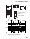
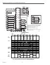
10. Make sure loads do not exceed the terminal ratings.
Refer to the label on the RM7800/RM7840 or to the
ratings in Tables 3, 4 and 5.
Final Wiring Check
1. Check the power supply circuit. The voltage and
frequency tolerance must match those of the
RM7800/RM7840. A separate power supply circuit may
be required for the RM7800/RM7840. Add the required
disconnect means and overload protection.
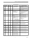
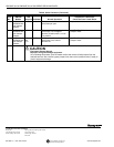
2. Check all wiring circuits and complete the Static
Checkout, see Table 8, before installing the
RM7800/RM7840 on the subbase.
3. Install all electrical connectors.
4.
Restore power to the panel.
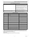
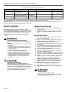
Table 1. Recommended Wire Sizes and Part Numbers.
Application Recommended Wire Size Recommended Part Number(s)
Line voltage terminals 14, 16 or 18 AWG copper conductor, 600
volt insulation, moisture-resistant wire.
TTW60C, THW75C, THHN90C.
Keyboard Display Module (KDM) 22 AWG two-wire twisted pair with
ground, or five wire.
Belden 8723 shielded cable or equivalent.
Data ControlBus Module™ 22 AWG two-wire twisted pair with
ground, or five wire.
Belden 8723 shielded cable or equivalent.
Remote Reset Module 22 AWG two-wire twisted pair, insulated
for low voltage.
—
Communications Interface ControlBus™
Module
22 AWG two-wire twisted pair with
ground.
Belden 8723 shielded cable or equivalent.
13 Vdc full-wave rectified transformer
power input.
18 AWG wire insulated for voltages and
temperatures for given application.
TTW60C, THW75C, THHN90C.