


RM7800E,G,L,M; RM7840E,G,L,M 7800 SERIES RELAY MODULES
15 66-1085—3
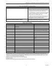
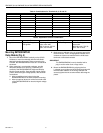
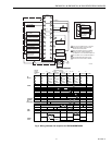
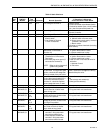
Table 8. Static Checkout.
Test
No.
RM7800/
RM7840
Models
Test
Jumpers Voltmeter Normal Operation
If Operation is Abnormal,
Check the Items Listed Below
1 All None 4-L2 Line voltage at Terminal 4. 1. Master Switch.
2. Power connected to the Master Switch.
3. Overload protection (fuse, circuit breaker,
etc.) has not opened the power line.
2 6-L2 Line voltage at Terminal 6. 1. Limits.
2. Burner Controller.
3 20-L2 Line voltage at Terminal 20. 1. Preignition interlocks.
4 4-5 7-L2 1. Burner motor (fan or
blower) starts.
2. Line voltage at Terminal
7 within 10 seconds.
1. Burner motor circuit.
a. Manual switch of burner motor.
b. Burner motor power supply, overload
protection, and starter.
c. Burner motor.
2. Running or Lockout Interlocks (including
Airflow Switch).
5 4-10 — Ignition spark (if ignition
transformer is connected to
Te r m in al 1 0 )
1. Watch for spark or listen for buzz.
a. Ignition electrodes are clean.
b. Ignition transformer is okay.
6 All 4-8 — 1. Ignition spark (if ignition
transformer is connected to
Terminal 8).
2. Automatic pilot valve opens (if
connected to Terminal 8).
NOTE: Refer to wiring diagram of
system being tested.
1. Watch for spark or listen for buzz.
a. Ignition electrodes are clean.
b. Ignition transformer is okay.
2. Listen for click or feel head of valve for
activation.
a. Actuator if used.
b. Pilot valve.
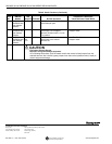
7 4-21 — Same as test no. 6 for connections
to Terminal 8. If using direct spark
ignition, check the first stage fuel
valve(s) instead of the pilot valve.
Same as test no. 6. If using direct spark
ignition, check the first stage fuel valve(s)
instead of the pilot valve.
8 4-9 — Automatic main fuel valve(s) open.
If using direct spark ignition on a
model with intermittent pilot on
Terminal 21, check the optional
second stage fuel valve, if used.
1. Listen for and observe operation of the
main
fuel valve(s) and actuator(s).
2. Valve(s) and actuator(s).
9 4-3 — Alarm (if used) turns on. 1. Alarm.
10 RM7800E,G,L;
RM7840E,G,L
4-5
and
12-13
18-L2 Firing rate motor drives open; zero
volts at Terminal 18 after motor
starts driving open.
1. Low Fire Start Switch.
2. Firing rate motor and transformer.
11 RM7800E,G,L;
RM7840E,G,L
4-5
and
14-13
18-L2 Firing rate motor drives closed; line
voltage at Terminal 18 after motor
is in Low Fire position.
1. Low Fire Start Switch.
2. Firing rate motor and transformer.
12 RM7800E,L;
RM7840E,L
4-5
and
12-13
19-L2 Firing rate motor drives open; line
voltage at Terminal 19 after motor
is in High Fire position.
1. High Fire Purge Switch.
2. Firing rate motor and transformer.
13 RM7800E,L;
RM7840E,L
4-5
and
14-13
19-L2 Firing rate motor drives closed;
zero volts at Terminal 19 after
motor starts driving closed.
1. Low Fire Start Switch.
2. Firing rate motor and transformer.
14 RM7800E,G,L;
RM7840E,G,L
15-13 — 1. Raise setpoint of Series 90
controller—firing rate motor
should drive toward open.
2. Lower setpoint of Series 90
controller—firing rate motor
should drive toward closed.
1. Series 90 Controller.
2. Firing rate motor and transformer.