


RM7800E,G,L,M; RM7840E,G,L,M 7800 SERIES RELAY MODULES
66-1085—3 12
Ignition Trials
1. Pilot Flame Establishing Period (PFEP):
a. With the firing rate motor at the low fire position:
(1) The pilot valve and ignition transformer,
terminals 8, 10 and 21, are energized. The
RM7800M has an intermittent pilot valve,
terminal 21. The RM7800/RM7840G has an
interrupted or intermittent pilot valve, terminal
21, depending on the selection of configuration
jumper 2. The RM7800/RM7840E,L has a
fifteen-second interrupted pilot valve, terminal
21. All of the RM7800/RM7840s have a
ten-second interrupted pilot valve/ignition,
terminal 8.
(2) During PFEP, the Low Fire Switch must remain
closed. If it opens, a safety shutdown occurs.
(3) The Preignition Interlock input is ignored
throughout the Ignition Trial state.
b. Flame must be proven by the end of the ten-second
PFEP (four if JR1 is clipped) to allow the sequence
to continue. If flame is not proven by the end of
PFEP, a safety shutdown occurs.
c. After five seconds, the ignition, terminal 10, is
de-energized for early spark termination.
2. Main Flame Establishing Period (MFEP):
a. Terminal 9 is energized when the presence of flame
is verified at the end of a 10-second Pilot Flame
Establishing Period (PFEP) (four seconds if JR1 is
clipped).
b. Terminal 8 is turned off 10 seconds after Terminal 9
is energized.
c. Terminal 21 action:
(1) RM7800E,L/RM7840E,L: De-energized
15 seconds after Terminal 9 is energized.
(2) RM7840G:
(a) Not turned off, or
(b)15 seconds after Terminal 9 is energized and
JR2 is clipped, or
(c)30 seconds after Terminal 9 is energized and
Terminals 5 and 19 are jumpered and jumper
JR2 is clipped.
(3) RM7800L1053, RM7840L1026,
RM7800M/RM7840M: Remain energized as
long as call for heat is present.
Run
1. A ten-second stabilization period occurs at the
beginning of the RUN period.
2.
The firing rate motor releases to modulation
(RM7800/RM7840E,G,L). Damper motor is energized
(RM7800/RM7840M).
3.
The RM7800/RM7840 is now in RUN and remains in
RUN until the controller input, terminal 6, opens,
indicating that the demand is satisfied or a limit opened.
Postpurge
The RM7800/RM7840 provides a fifteen-second
POSTPURGE following the completion of the RUN period.
The blower motor output is powered to drive all products of
combustion and any unburned fuel from the combustion
chamber. It also supplies combustion air to burn fuel being
purged from the fuel line downstream of the fuel shutoff valve.
1.
The main fuel valve and intermittent pilot valve,
Terminals 9 and 21, are de-energized and the firing rate
motor is commanded to the low fire position to begin the
POSTPURGE period.
2. The Preignition Interlock closes within the first five
seconds of POSTPURGE.
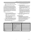
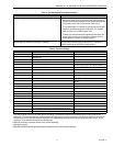
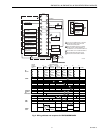
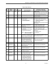
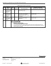
Table 6. Sequence Timing for Normal Operation.
* STANDBY and RUN can be an infinite time period.
**PURGE determined by which ST7800A purge card is selected.
a
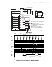
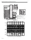
The MFEP is determined by which terminal is used, configuration jumper selected or jumper wire added.
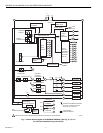
See Fig. 2, 3, 4, 5 and 6.
b
RM7800L1053, RM7840L1026: 10 second or intermittent.
Device Initiate Standby Purge
Flame Establishing
Period
Run
Post-
Purge
Timing
Interlock
Circuits
Firing
Rate
Circuit
Energy
Saving
Prepurge
Approval
Code
BodiesPilot Main
a
RM7800E/
RM7840E
10 sec.. * ** 4 or 10
sec.
10 or 15
sec.
* 15 sec. Preignition,
Lockout,
High and
Low Fire
4-wire
modulating
Yes FM/IRI
Modulating
RM7800G/
RM7840G
10, 15 sec.
or
intermittent
Preignition,
Running,
Low Fire
No UL/CSA
Modulating
RM7800L/
RM7840L
10 or 15
sec.
b
Preignition,
Lockout,
High and
Low Fire
FM/IRI
Modulating
RM7800M/
RM7840M
10 sec. or
intermittent
Preignition,
Running,
Low Fire
2-wire
isolated
On-Off-On
contacts
UL/CSA
On-Off