


RM7800E,G,L,M; RM7840E,G,L,M 7800 SERIES RELAY MODULES
66-1085—3 14
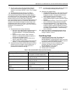
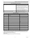
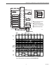
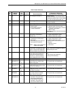
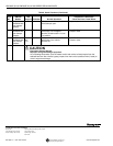
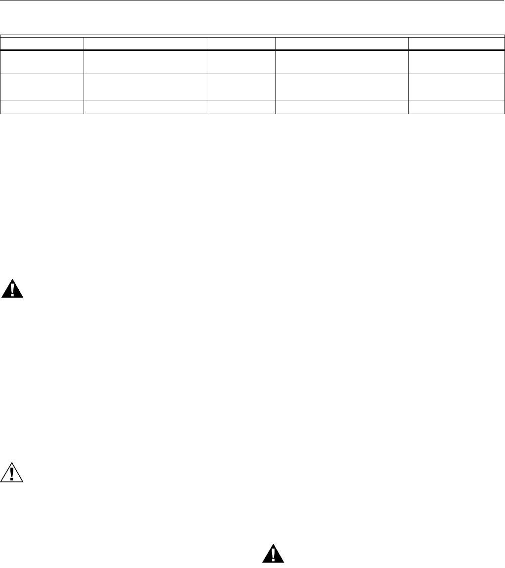
Table 7. Site Configurable Jumper Options.
a
Pilot Valve /First Stage Oil Valve (Valve/Start) Terminal 21.
b
A 30 second MFEP can be accomplished by adding a jumper wire between Terminals 19 and 5.
SERVICE NOTE:Clipping and removing a site-configurable jumper enhances the level of safety. Removal after 200 hours of
main valve operation will result in a hard lockout, Code 110.
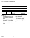
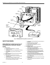
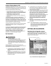
STATIC CHECKOUT
After checking all wiring, perform this checkout before
installing the RM7800/RM7840 on the subbase. These tests
verify the Q7800 Wiring Subbase is wired correctly, and the
external controllers, limits, interlocks, actuators, valves,
transformers, motors and other devices are operating
properly.
WARNING
Explosion and Electrical Shock Hazard.
Can cause serious injury, death or equipment
damage.
1. Close all manual fuel shutoff valve(s) before starting
these tests.
2. Use extreme care while testing the system. Line
voltage is present on most terminal connections
when power is on.
3.
Open the master switch before installing or
removing a jumper on the subbase.
4.
Before continuing to the next test, be sure to
remove test jumper(s) used in the previous test.
5. Replace all limits and interlocks that are not
operating properly. Do not bypass limits and
interlocks.
CAUTION
Equipment Damage Hazard.
Improper testing can damage equipment.
Internal surge protectors can break down and conduct
a current, causing the RM7800/RM7840 to fail the
dielectric test or possibly destroy the internal lightning
and high current protection. Do not perform a dielectric
test with the RM7800/RM7840 installed.
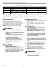
Equipment Recommended
1.
Voltmeter (1M ohm/volt minimum sensitivity) set on the
0-300 Vac scale.
2. Two jumper wires; no. 14 wire, insulated, 12 inches
(304.8 mm) long with insulated alligator clips at both
ends.
General Instructions
1. Perform all applicable tests listed in Static Checkout,
Table 8, in the order listed.
2.
Make sure all manual fuel shutoff valve(s) are closed.
3. Perform only those tests designated for the specific
RM7800/RM7840 model being tested.
4. Raise the setpoint of the operating controller to simulate
a call for heat.
5.
For each test, open the master switch and install the
jumper wire(s) between the subbase wiring terminals
listed in the Test Jumpers column.
6.
Close the master switch before observing operation.
7. Read the voltage between the subbase wiring terminals
listed in the Voltmeter column.
8. If there is no voltage or the operation is abnormal, check
the circuits and external devices as described in the last
column.
9.
Check all wiring for correct connections, tight terminal
screws, correct wire, and proper wiring techniques.
Replace all damaged or incorrectly sized wires.
10.
Replace faulty controllers, limits, interlocks, actuators,
valves, transformers, motors and other devices as
required.
11. Make sure normal operation is obtained for each
required test before continuing the checkout.
12. After completing each test, be sure to remove the test
jumper(s).
WARNING
Explosion Hazard.
Can cause serious injury or death.
Make sure all manual fuel shutoff valves are closed
before performing static checkout.
Jumper Number Description Intact Clipped RM7800/RM7840 Type
JR1 Pilot Flame Establishing
Period (PFEP)
10 seconds 4 seconds All
JR2
Pilot Valve
a
/Main Flame
Establishing Period (MFEP)
10 seconds
Intermittent
15 or 30 seconds Interrupted
b
RM7800G/RM7840G
JR3 Start-up Interlock Check Disabled Enabled All