


RM7800E,G,L,M; RM7840E,G,L,M 7800 SERIES RELAY MODULES
5 66-1085—3
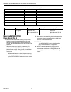
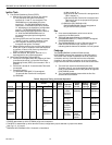
Table 2. Recommended Grounding Practices.
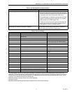
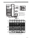
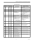
Table 3. Terminal Ratings.
.
a
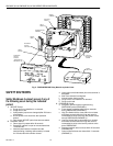
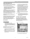
The relay module must have an earth ground providing a connection between the subbase and the control panel or the
equipment. The earth ground wire must be capable of conducting the current to blow the 15A fuse (or breaker) in event of an
internal short circuit. The relay module requires a low impedance ground connection to the equipment frame, which, in turn,
requires a low impedance connection to earth ground.
b
2000 VA maximum connected load to relay module assembly.
c
See tables 4 and 5.
d
RM7800G,M/RM7840G,M operating frequency determined by relay module selection.
Ground Type Recommended Practice
Earth ground (subbase and relay module). 1. Use to provide a connection between the subbase and
the control panel of the equipment. Earth ground must be
capable of conducting enough current to blow the 20A fuse
(or breaker) in the event of an internal short circuit.
2. Use wide straps or brackets to provide minimum length,
maximum surface area ground conductors. If a leadwire
must be used, use 14 AWG copper wire.
3. Make sure that mechanically tightened joints along the
ground path are free of nonconductive coatings and pro-
tected against corrosion on mating surfaces.
Signal ground (KDM, Data ControlBus Module™,
Communications Interface ControlBus™ Module).
Use the shield of the signal wire to ground the device to the
signal ground terminals [3(c)] of each device. Connect the
shield at both ends of the chain to earth ground.
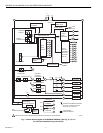
Terminal No. Description Ratings
G
Flame Sensor Ground
a
—
Earth G
Earth Ground
a
—
L2(N) Line Voltage Common —
3 Alarm 120 Vac, 1A pilot duty.
4 Line Voltage Supply (L1)
120 Vac (+10%/-15%), 50 or 60 Hz (±10%)
b,d
5 Burner Motor 120 Vac, 9.8 AFL, 58.8 ALR (inrush).
6 Burner Controller and Limits 120 Vac, 1 mA.
7 Lockout/Running Interlock 120 Vac, 8A run, 43A inrush.
8 Pilot Valve/Ignition
120 Vac
c
.
9 Main Fuel Valve
120 Vac
c
.
10 Ignition
120 Vac
c
.
F(11) Flame Sensor 60 to 220 Vac, current limited.
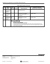
12 Firing Rate High Fire 120 Vac, 75 VA pilot duty.
13 Firing Rate Common 120 Vac, 75 VA pilot duty.
14 Firing Rate Low Fire 120 Vac, 75 VA pilot duty.
15 Firing Rate Modulate 120 Vac, 75 VA pilot duty.
16 Unused —
17 Unused —
18 Low Fire Switch Input 120 Vac, 1 mA.
19 High Fire Switch Input 120 Vac, 1 mA.
20 Preignition Interlock Input 120 Vac, 1 mA.
21 Interrupted/Intermittent Pilot Valve/First Stage Oil Valve
120 Vac
c
.
22 Shutter 120 Vac, 0.5A.