


RM7800E,G,L,M; RM7840E,G,L,M 7800 SERIES RELAY MODULES
66-1085—3 2
WARNING
Fire or Explosion Hazard.
Can cause property damage, severe injury,
or death.
To prevent possible hazardous burner operation, verify
safety requirements each time a control is installed on
a burner.
WARNING
Electrical Shock Hazard.
Can cause serious injury or death.
Disconnect the power supply before beginning
installation. More than one power supply disconnect
may be required.
IMPORTANT
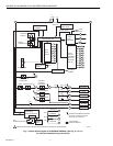
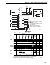
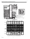
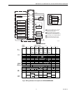
1. Wiring connections for the relay modules are unique;
therefore, refer to Fig. 2, 3, 4, or the correct
Specifications for proper subbase wiring, and
sequence charts.
2. Wiring must comply with all applicable codes,
ordinances and regulations.
3. Wiring must comply with NEC Class 1 (Line Voltage)
wiring.
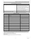
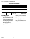
4. Loads connected to the RM7800/RM7840 must not
exceed those listed on the RM7800/RM7840 label or
the Specifications, see Table 1.
5. Limits and interlocks must be rated to simultaneously
carry and break current to the ignition transformer,
pilot valve, and main fuel valve(s).
6. All external timers must be listed or component
recognized by authorities who have jurisdiction for
the specific purpose for which they are used.
7. For on-off gas-fired systems, some authorities who
have jurisdiction prohibit the wiring of any limit or
operating contacts in series between the flame
safeguard control and the main fuel valve(s).
8. Two Flame Detectors can be connected in parallel
with the exception of Infrared Flame Detectors
(C7015).
9. This equipment generates, uses and can radiate
radio frequency energy and, if not installed and used
in accordance with the instructions, may cause
interference to radio communications. It has been
tested and found to comply with the limits for a
Class B computing device of Part 15 of FCC rules
which are designed to provide reasonable protection
against such interference when operated in a
commercial environment. Operation of this
equipment in a residential area may cause
interference; in which case, the users at their own
expense may be required to take whatever
measures are required to correct this interference.
10.This digital apparatus does not exceed the Class B
limits for radio noise for digital apparatus set out in
the Radio Interference Regulations of the Canadian
Department of Communications.
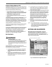
Location
Humidity
Install the relay module where the relative humidity never
reaches the saturation point. The relay module is designed to
operate in a maximum 85 percent relative humidity
continuous, noncondensing, moisture environment.
Condensing moisture may cause a safety shutdown.
Vibration
Do not install the relay module where it could be subjected to
vibration in excess of 0.5G continuous maximum vibration.
Weather
The relay module is not designed to be weather tight.
When installed outdoors, protect the relay module using an
approved weather-tight enclosure.
Mounting Wiring Subbase
1.
Mount the subbase in any position except horizontally
with the bifurcated contacts pointing down. The
standard vertical position is recommended. Any other
position decreases the maximum ambient temperature
rating.
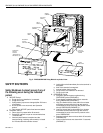
2. Select a location on a wall, burner or electrical panel.
The Q7800 can be mounted directly in the control
cabinet. Be sure to allow adequate clearance for
servicing, installation, access or removal of the
RM7800/RM7840, Expanded Annunciator, Keyboard
Display Module, flame amplifier, flame amplifier signal
voltage probes, Run/Test Switch, electrical signal
voltage probes and electrical field connections.
3. For surface mounting, use the back of the subbase as a
template to mark the four screw locations. Drill the pilot
holes.
4. Securely mount the subbase using four no. 6 screws.
Wiring Subbase
WARNING
Electrical Shock Hazard.
Can cause serious injury, death or equipment
damage.
Disconnect the power supply before beginning
installation to prevent electrical shock, equipment
and control damage. More than one power supply
disconnect may be required.
1. For proper subbase wiring, refer to Figs. 2, 3, 4 or 5.
2. For proper remote wiring of the Keyboard Display
Module, through a 203541 5-wire Connector, refer to
the Specifications for the Keyboard Display Module
(65-0090), Network Interface Unit
(63-2278), Data ControlBus Module™ (65-0091) or
Extension Cable Assembly (65-0131).
3.
Disconnect the power supply from the main disconnect
before beginning installation to prevent electrical shock
and equipment damage. More than one disconnect may
be required.