


60-2285—7 6
R4795A
INSTALLATION
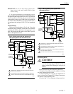
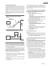
Replacing RA890E,F,G with R4795A
1. Disconnect all wires from terminal 1, and splice with
solderless connector. (If RA890 has no terminal 1 wiring,
disregard this step.)
2. Remove line voltage controller wire from terminal 6
and connect to terminal 1.
3. Move burner motor connection from terminal 3 to ter-
minal 6 on subbase.
4. Remove jumper from T and T and install air switch. If
low voltage control was wired to RA890 T-T, remove low
voltage control and install line voltage control as shown in
Fig. 4.
5. If R482D Relay was used with RA890E, remove it.
The R482D is redundant when R4795D is used.
6. Check for proper operation through at least two cycles.
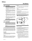
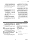
Fig. 4—Replacing RA890E,F,G with R4795A on
gas or oil burner.
L1
(HOT)
L2
REPLACING RA890 WITH R4795 ON GAS OR OIL BURNER
CONTROLLER HIGH LIMIT
MAIN GAS
VALVE OR
2ND STAGE
OIL VALVE
IGNITION
TRANSFORMER
BURNER
MOTOR
PILOT OR
OIL VALVE
RA890 WITH Q270
BEFORE
FLAME
DETECTOR
6
T
T
F
G
2
1
3
4
5
L1
(HOT)
L2
CONTROLLER HIGH LIMIT
MAIN GAS
VALVE OR
2ND STAGE
OIL VALVE
IGNITION
TRANSFORMER
BURNER
MOTOR
PILOT OR
OIL VALVE
RA4795 WITH Q270
AFTER
FLAME
DETECTOR
6
8
7
6
T
T
F
G
2
1
3
4
5
AIR FLOW
SWITCH
SODERLESS
CONNECTION
120V
120V
M8684
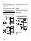
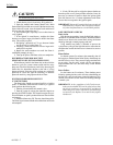
R4795C Replacement
In most cases, the R4795A can directly replace the
R4795C. For standing pilot applications where the pilot
flame was detected during the off cycle, install a relay as
shown in Fig. 5.
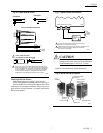
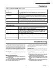
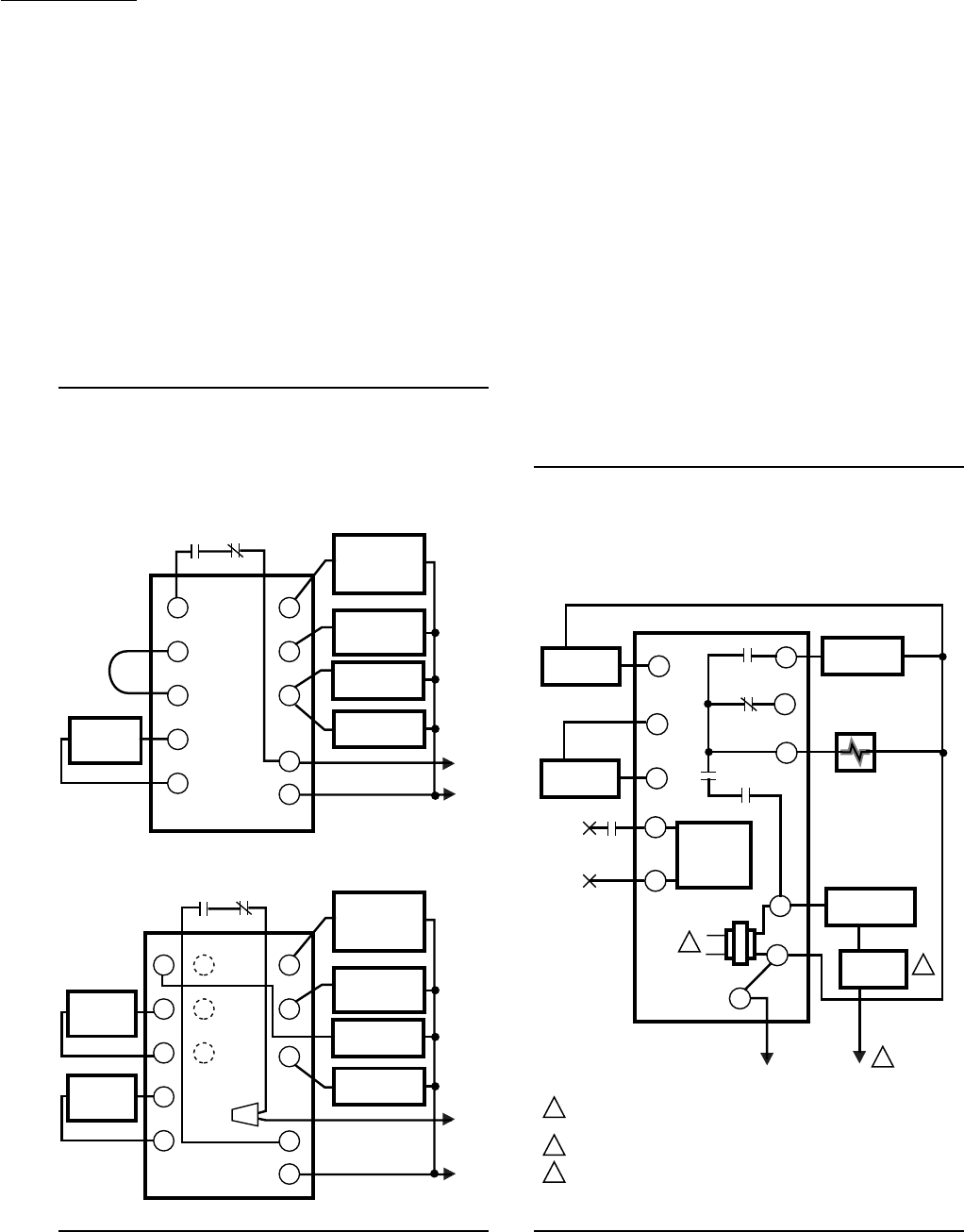
Flame Detector Wiring
See Fig. 6.
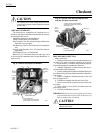
Alarm Contacts
Models with alarm contacts have three male quick-con-
nect terminals. Three female quick-connect terminals are
provided for field installation. To connect leadwires to the
female quick-connects, strip 1/4 inch (6.4 mm) insulation
from end of leadwire; insert into the quick-connect, and
crimp securely with a crimping tool. Fig. 7 shows proper
alarm terminal connections.
If a line voltage alarm is used with the R4795, mount the
entire control in a suitable enclosure.
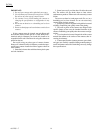
Fig. 5—When R4795A replaces R4795C in a
standing pilot application, install relay 1R to
prevent detection of pilot flame during burner
off cycle.
M8685
L1
(HOT)
L2
1
1
2
3
POWER SUPPLY. PROVIDE DISCONNECT MEANS AND OVERLOAD
PROTECTION AS REQUIRED.
REFER TO SPECIFICATIONS SECTION FOR RECOMMENDED LIMITS.
LOW VOLTAGE CIRCUIT OMITTED.
BURNER
MOTOR
AIR FLOW
SWITCH
TO FLAME
DETECTOR
(FLAME ROD
OR UV
DETECTOR)
FLAME
AMPLIFIER
1K4
3K2
1R1
2K2
2K3
MIAN FUEL
VALVES
CONTROLLER
LIMIT(S)
8
7
6
F
G
5
4
3
1
2
2
3
1R
R4795A