60-2285—7 12
R4795A
TROUBLESHOOTING
F. Pilot lights and relay 2K pulls in but the main burner
does not light.
G. Relay 2K remains in after flame is extinguished.
H. Miscellaneous problems:
1. Repeated lockouts or control failures.
2. Ignition interference (flame rod installations only).
TROUBLESHOOTING PROCEDURES
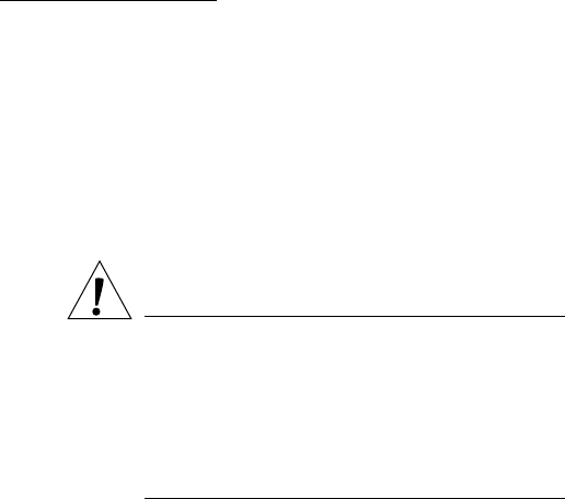
CAUTION
1. Use extreme care while troubleshooting the
R4795; line voltage is present on most contacts
when power is On.
2. Open the master switch before removing the
cover, cleaning contacts, removing R4795 from
subbase, or reinstalling R4795 on subbase. See
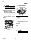
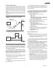
Fig. 9 for relay location.
IMPORTANT:
1. Clean contacts only when instructed to do so in a
troubleshooting procedure. Follow the instructions in
Contact Cleaning section.
2. If, after completing an applicable Troubleshooting
Procedure, proper operation still cannot be obtained,
replace the R4795 (except amplifier and purge timer,
unless noted).
A. Relay 3K does not pull in on a call for heat
1. Check for power at terminals 1 and 2 with the control-
ler calling for heat.
a. Voltage must be within plus 10 to minus 15 percent
of the rated voltage for dependable operation.
b. If voltage is zero, check the continuity of the limit
and controller contacts and check the power sup-
ply. Look for blown fuses, open switches, and bad
wiring connections.
2. If voltage at terminals 1 and 2 is satisfactory and relay
3K will not pull in, clean the 1K and 3K relay contacts.
Press safety switch button several times to clean the
contacts. If trouble persists, replace the R4795.
B. Relay 3K pulls in but the burner motor does not start
1. Check for power at terminal 8 when the 3K relay
pulls in.
a. If terminal 8 is not powered, clean the 3K relay
contacts and recheck for power. If terminal 8 can-
not be powered, replace the R4795.
b. If terminal 8 is powered, check the fan or burner
motor.
C. Burner motor starts but prepurge does not stop at end
of purge timing (relay 1K does not pull in)
1. Check the seating of the plug-in purge timer.
2. Check that the airflow switch contacts are making.
Approximately 20 Vdc should appear between termi-
nals 7 (plus) and G (minus) when airflow switch con-
tacts are made.
3. Check the position of the flame relay. If relay 2K is
pulled in, check for flame simulating condition.
4. If the flame relay is not pulled in, clean the 2K relay
contacts.
5. Replace the purge timer with one of the same timing.
If problem still continues, replace the R4795.
D. Relay 1K pulls in but the pilot does not light, ignition
does not occur, or expanding pilot valve does not open
1. Make sure that all manual fuel valves are open.
2. Check voltage between terminals 3 and 2, or 4 and 2,
as applicable. (Terminal 3 is used for pilot or first stage
oil valve; terminal 4 for ignition.) Check must be made
before control locks out on safety.
3. If zero voltage, clean the 1K and 2K relay contacts;
then recycle the system and recheck the voltage at ter-
minal 3 or 4. If terminals cannot be powered, replace the
R4795.
4. If correct voltage at terminals 3 and 4, check the pilot
valve and ignition and the circuits.
E. Pilot lights but relay 2K does not pull in (control locks
out without lighting the main burner)
1. Use a 121708 Rectification or a 203659 or 123514B
Ultraviolet Flame Simulator to check the flame relay.
Follow the instructions for the simulator.
2. If no flame simulator is available, do a flame current
check. If the flame current is satisfactory, replace the
R4795. If the flame current is not satisfactory, recheck
all items.
F. Pilot lights and relay 2K pulls in but the main burner
does not light
1. Check that the manual main fuel valves are all open.
2. Check the voltage at terminal 5 when the 2K relay
pulls in.
a. If normal voltage at terminal 5, check the main
valve and the external valve circuit.
b. If zero voltage at terminal 5, clean the 2K relay
contacts. If terminal 4 cannot be powered, replace
the R4795.
G. Relay 2K remains in after flame is extinguished
1. If the flame detector is a rectifying flame rod, install a
new plug-in amplifier.
2. If the flame detector is a rectifying photocell or C7012
Ultraviolet Detector, plug the back end of the flame
simulator into the jack of the plug-in amplifier.
a. If that does not cause relay 2K to drop out, install a
new plug-in amplifier.
b. If plugging into the meter jack causes relay 2K to
drop out, the trouble is caused by hot refractory
hold-in, detector failure, or other flame simulating
conditions.
(1) Resight the photocell at a cooler or more re-
mote area of the refractory.
(2) Recheck the flame detector current for the
condition recommended in the Checkout sec-
tion. Replace the detector if necessary.


