


5 60-2285—7
R4795A
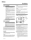
INSTALLATION
IMPORTANT: Do not run high voltage ignition trans-
former wires in the same conduit with the flame
detector wiring.
5. For ignition installations in a contaminating environ-
ment, use Honeywell Specification no. R1239001 High Ten-
sion Ignition Cable or equivalent. This wire is very resistant
to severe conditions of oil, heat, and corona, and is tested to
withstand high voltages up to 25,000V rms in a salt bath for
one minute without breakdown. It is rated at 200°F (93°C)
for continuous duty and up to 350°F (75°C) for intermittent
use.
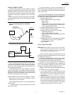
Wiring Hookups
The typical wiring hookups in Fig. 2 and 3 show the
internal line voltage schematic. Contact 3K2 closes when the
controller calls for heat. 1K4 closes when prepurge is com-
plete. 2K2 breaks and 2K3 makes when flame is proven.
Also see the Operation section.
Fig. 2—Wiring hookup of gas system with
interrupted ignition and intermittent pilot.
M8682
L1
(HOT)
L2
1
1
2
3
POWER SUPPLY. PROVIDE DISCONNECT MEANS AND OVERLOAD
PROTECTION AS REQUIRED.
FOR INTERMITTENT IGNITION, CONNECT IGNITION TO TERMINAL 3.
REFER TO SPECIFICATIONS SECTION FOR RECOMMENDED LIMITS.
BURNER
MOTOR
AIR FLOW
SWITCH
TO FLAME
DETECTOR
(FLAME ROD
OR UV
DETECTOR)
FLAME
AMPLIFIER
1K4
3K2
2K2
2K3
MAIN FUEL
VALVE(S)
IGNITION
PILOT
VALVE
CONTROLLER
LIMIT(S)
R4795A
8
7
6
F
G
5
4
3
1
2
2
3
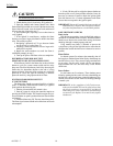
Fig. 3—Wiring hookup of oil system with
interrupted ignition.
M8683
L1
(HOT)
L2
1
1
2
3
4
5
POWER SUPPLY. PROVIDE DISCONNECT MEANS AND OVERLOAD
PROTECTION AS REQUIRED.
FOR INTERMITTENT IGNITION,CONNECT IGNITION TO TERMINAL 3.
IMMEDIATE OPENING OIL VALVE V4046B.
OPTIONAL DELAYED OPENING OIL VALVE V4046A OR V4046B WITH
ST70A ELECTRONIC TIME DELAY.
REFER TO SPECIFICATIONS SECTION FOR RECOMMENDED LIMITS.
BURNER
MOTOR
AIR FLOW
SWITCH
TO FLAME
DETECTOR
(PHOTOCELL
OR UV)
FLAME
AMPLIFIER
1K4
3K2
2K2
2K3
2ND STAGE
OIL VALVE(S)
IGNITION
1ST STAGE
OIL VALVE(S)
CONTROLLER
LIMIT(S)
R4795A
8
7
6
F
G
5
4
3
1
2
2
5
3
4
Retrofitting R4795
CAUTION
Make wiring connections as specified in Fig. 2, 3,
or 4. Do not simply plug the R4795 into the old
subbase without first changing the wiring at the
subbase.
Observe the following when retrofitting the R4795:
1. Requires a line voltage controller capable of switching
the entire connected electrical load.
2. Delayed opening oil valve may be retained but its
delay is not necessary. Integral ST71A Purge Timer meets
the intent of a delayed opening valve.
3. Refer to Fig. 2, 3 or 4 for proper wiring connections.