


13 60-2285—7
R4795A
TROUBLESHOOTING • SERVICE
(3) Remove any flame simulating condition such
as false light.
(4) Note that any change made in the detector or its
sighting requires a pilot turndown test.
3. If using an R7290 Ultraviolet Amplifier, replace the
amplifier and recheck the flame relay dropout time. If
the flame relay dropout timing is still excessive, re-
place the detector and check its wiring.
4. If trouble persists, replace the R4795.
H. Miscellaneous problems
1. Repeated lockouts or control failures: The most com-
mon causes of repeated failures of the control or flame
detector, or repeated lockouts are:
a. High ambient temperatures over 125°F (52°C).
Subtract 10°F (6°C) for alarm contacts and 10°F
(6°C) for 50 Hz operation. -40°F (-40°C) models
have a maximum ambient of +115°F (46°C) at
60 Hz, +105°F (40°C) at 50 Hz.
b. Supply voltage variation greater than plus 10 to
minus 15 percent.
c. Marginal flame signal.
d. Faulty flame detector.
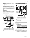
2. Ignition interference (flame rod installations only)
What it is. Ignition interference is a false signal
from a spark ignition source superimposed on the
basic flame signal. It is normally associated with a
marginal flame reading, and usually caused by a mar-
ginal flame ground.
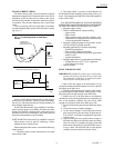
How detected. The arc gap circuit in the rectifica-
tion amplifier (Fig. 10) protects the R4795 from igni-
tion interference; however, it also prevents operations
when ignition interference is present above the arcing
level of the device. If a shutdown is caused by ignition
interference, the arc gap protector glows.
Continuous interference below the arcing level can
be detected by reading the flame current with the pilot
and ignition on; then with only the pilot on. Any sub-
stantial difference indicates the presence of ignition
interference.
Intermittent ignition interference may be due to
very turbulent air in the ignition electrode area. For
arc-over elsewhere, examine the electrodes for spac-
ing and for unusual dirt conditions or dust accumula-
tions between the ignition leads and flame leads.
How eliminated (tabulated in order of importance).
1. Provide adequate flame grounding area.
2. Be sure the ignition electrode and the flame rod
are on opposite sides of the grounding area.
3. Check for the correct spacings on the ignition
electrode. Spacing should be 1/16 in. (1.6 mm)
to 3/32 in. (2.4 mm) for 6,000V systems; 1/8 in.
(3.2 mm) to 3/16 in. (4.8 mm) for 10,000V
systems.
4. Eliminate any marginal spacings at other areas
along the lead routes. Replace any deteriorated
leads.
Service
GENERAL
1. Only qualified personnel should attempt to service
heating equipment or controls.
2. Perform all checks required in the Checkout section
when replacing the R4795, or when relighting or restoring
power to the system after shutdown.
3. Captive mounting screws carry current; always dis-
connect power before loosening or tightening the mounting
screws.
4. On each service call, check the controller for the ap-
proximately correct calibration and differential; assure it is
mounted securely (see Controller installation instructions).
5. Never use oil on any part of the R4795.
6. When cleaning the burner, clean the flame detector.
7. DO NOT MANUALLY PUSH IN THE R4795
RELAYS. This may damage the relays and it is an unsafe
practice because it overrides the protective features of the
relays. Clean relay contacts only as instructed following.
PERIODIC MAINTENANCE
The specific maintenance schedule setup will depend on
several factors including type of equipment being controlled,
operating conditions (dirt and heat especially), and the cost of
a nuisance shutdown. Include the following in any program:
Annually replace the vacuum tubes in the C7012 Flame
Detector (if used).
Perform a flame failure check and pilot turndown test
whenever the burner is serviced, and at least annually.
Inspect and clean the detector and any viewing windows
as often as required by soot accumulation and heat
conditions at the detector.
Do a flame current check at least monthly, and more often
where a shutdown may be costly.
Clean contacts only when required by failure to operate
properly.
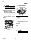
CONTACT CLEANING
CAUTION
Open the master switch before removing cover or
cleaning contacts. Line voltage is present on most
contacts when power is on.