


60-2285—7 4
R4795A
INSTALLATION
Installation
Vibration
Do not install the R4795A where it could be subject to
excessive vibration. Vibration shortens the life of the elec-
tronic and mechanical components.
Weather
The R4795A is not designed to be weathertight. If it is
installed outdoors, use a suitable weathertight enclosure.
Mounting The Subbase
Locate the subbase where ambient temperature is within
the specified rating.
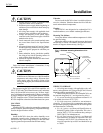
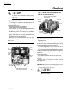
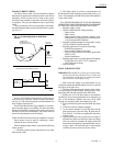
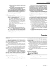
Mount the subbase so the top and bottom are horizontal
and the back is vertical. The subbase can lean backward as
much as 45 degrees when necessary. See Fig. 1.
Fig. 1—Subbase mounting dimensions in in.
(mm).
CAUTION
1. Installer must be a trained, experienced, flame
safeguard control service technician.
2. Disconnect power supply before beginning in-
stallation to prevent electrical shock and equip-
ment damage.
3. All wiring must comply with applicable local
electrical codes, ordinances, and regulations.
4. Voltage and frequency of the power supply
connected to this control must agree with those
marked on the device.
5. Loads connected to the control terminals must
not exceed those listed in the Specifications
section.
6. All external timers must be Listed or Compo-
nent Recognized by authorities having jurisdic-
tion for the specific purpose for which they are
used.
7. Some authorities having jurisdiction prohibit
the wiring of any limit or operating contacts in
series with the main fuel valve(s).
8. Perform all required checkout tests after instal-
lation is complete.
Follow the burner manufacturer’s instructions, if sup-
plied. Otherwise proceed as follows.
CAUTION
Ultraviolet sensing tubes have a life expectancy of
40,000 hours of continuous use within the ambient
temperature and voltage ratings. Worn out ultra-
violet sensing tubes can result in failure of the
sensing tube to properly discriminate between flame
conditions.
For systems using R4795A with R7290 Amplifiers, use
C7027, C7035 and C7044 Flame Detectors only on burners
that cycle On and Off at least once every 24 hours. Appli-
ances with burners that remain on for 24 hours continuously
or longer should use the C7012E Flame Detector with the
R7247C Amplifier or the C7076A Flame Detector with the
R7476A Amplifier as the ultraviolet flame detection system.
LOCATION
Temperature
Install the R4795A where the surrounding temperatures
remain within the Ambient Operating Temperature Ratings
listed in the Specifications section.
Humidity
Install the R4795A where the relative humidity never
reaches the saturation point. Condensation of moisture on
the R4795A may cause enough leakage to short the flame
signal to ground and prevent the burner from starting.
M8681
HORIZONTAL
VERTICAL
2-7/8
(73.0)
4-1/8 (104.8)
KNOCKOUTS (9) FOR
1/2 IN. (13) CONDUIT
45 DEGREES
MAXIMUM LEAN
WIRING TO SUBBASE
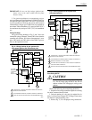
1. All wiring must comply with applicable codes, ordi-
nances, and regulations. All wiring to the Q270A Universal
Mounting subbase must be NEC Class 1.
2. When wiring the Q270A for use with the R4795A, use
the terminal designations 8, 7, and 6 (printed in yellow).
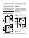
3. For normal installations, use moisture-resistant No. 14
wire suitable for at least 167°F (75°C).
4. For high temperature installations, use moisture-re-
sistant No. 14 wire selected for a temperature rating above
the maximum operating temperature for all but the ignition
and flame detector F leadwires.
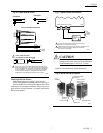
a. For the ignition, use Honeywell Specification no.
R1061012 Ignition Cable or equivalent. This wire is
rated at 350°F (175°C) for continuous duty, and up to
500°F (260°C) for intermittent use.
b. For the flame detector F leadwire, use Honeywell
Specification no. R1298020 or equivalent. This wire
is rated up to 400°F (205°C) for continuous duty. It is
tested for operation up to 600V and breakdown up
to 7500V.