


MS-9600LS Series Manual — P/N 52646:B2 2/12/2010 59
Optional Modules and Devices Installation
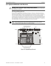
installation details. Refer to “ANN-BUS Options” on page 121 for programming information.
Installation
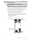
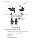
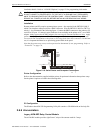
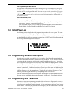
Remote printers and PCs require separate primary power. Also required is the PRT/PK-CABLE
which is an interface cable prewired to a DB9F connector. Wire the PRT/PK-CABLE to TB7 Ter-
minals 1 - 4 as illustrated in the following figure. Connect the DB9F connector to the printer or PC
serial EIA-232 port. If a nine-pin serial connector is not available on the printer or PC, use a DB25
adapter. Make certain that the DB25 adapter does not swap the Transmit and Receive lines.
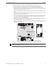
Apply
power to the FACP and printer or PC. Note that a ground fault (zero impedance to ground) may
occur on the FACP, dependent on the printer or PC being used, due to this connection. For this rea-
son, it is important that there be no preexisting ground fault on the panel.
Note that the printer may or may not be supervised as determined by user programming. Refer to
“Printer/PC” on page 134.
Printer Configuration
Refer to the documentation supplied with the printer for pertinent information about printer setup.
Set the printer’s options as listed in the following table:
PC Configuration
The Windows-based PK-CD Programming Utility Kit contains a CD-ROM with on-line help file.
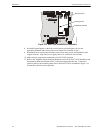
2.6.6 Annunciators
Legacy ACM-8RF Relay Control Module
The ACM-8RF module provides eight Form-C relays with contacts rated for 5 amps.
!
CAUTION: POSSIBLE EQUIPMENT DAMAGE
DO NOT CONNECT A PRINTER OR PC TO THE FACP IF A GROUND FAULT (ZERO IMPED-
ANCE TO GROUND) EXISTS ON THE CONTROL PANEL. CIRCUIT DAMAGE MAY RESULT.
REMOVE ALL POWER (AC AND DC) BEFORE INSTALLING OR REMOVING ANY WIRING.
COMMUNICATION SETUP
BUFFER: LARGE
DATA BITS: 7
PARITY: EVEN
STOP BIT: 1 STOP
BAUD RATE: 2400/4800/9600
AUTOMATIC LINE FEED NO
AUTOMATIC CARRIAGE RETURN NO
RS-232 PC/PRINTER
B+ A+ B- A- B A
1 COMM 2
ACS
SHIELD
SLC SLC
XMT RCV DTR GRND
T
B
7
T
B
6
T
B
8
RCV
DTR
GRND
TX
5 4 3 2 1
9 8 7 6
Figure 2.18 Serial Printer and Computer Connections
PRT/PK-CABLE
9600tb7a.wmf
Red
White
Green
Black