


MS-9600LS Series Manual — P/N 52646:B2 2/12/2010 53
Optional Modules and Devices Installation
The following steps must be followed when installing the DACT-UD2 module:
1. Remove all power (AC and DC) from FACP before proceeding with installation
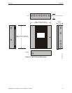
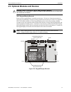
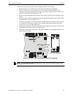
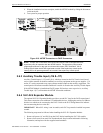
2. Remove all main circuit board mounting screws (6 locations) and the 4XTMF module
standoffs (2 locations), unplug the power supply cable from J1 and lift the main circuit board
assembly off the chassis (refer to Figure 2.10)
3. Remove the Keypad/Display from the main circuit board as described in the beginning of this
section
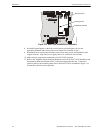
4. Remove and discard the Keypad/Display support standoff that presently occupies DACT-UD2
standoff location #3 (refer to Figure 2.12)
5. Install the supplied DACT-UD2 female/female standoffs in the three locations shown in Figure
2.12 and secure with the three supplied screws, inserted from the bottom side of the main
circuit board. Be sure to tighten them fully.
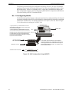
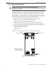
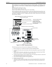
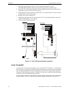
6. Carefully plug connector J5 on back of the DACT-UD2 module into connector J2 on the FACP
main circuit board, being careful not to bend any pins
7. Align the mounting holes in the DACT-UD2 module with the newly installed standoffs on the
FACP main circuit board
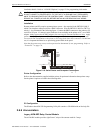
Secure the mod ule to the standoffs on the main circuit board with tw o of the screws supplie d with the DACT-UD2 and the supplie d male/female standoff wh ich becomes the new Keyp ad/Display support in th at locatio n ( see Figure 2.13)
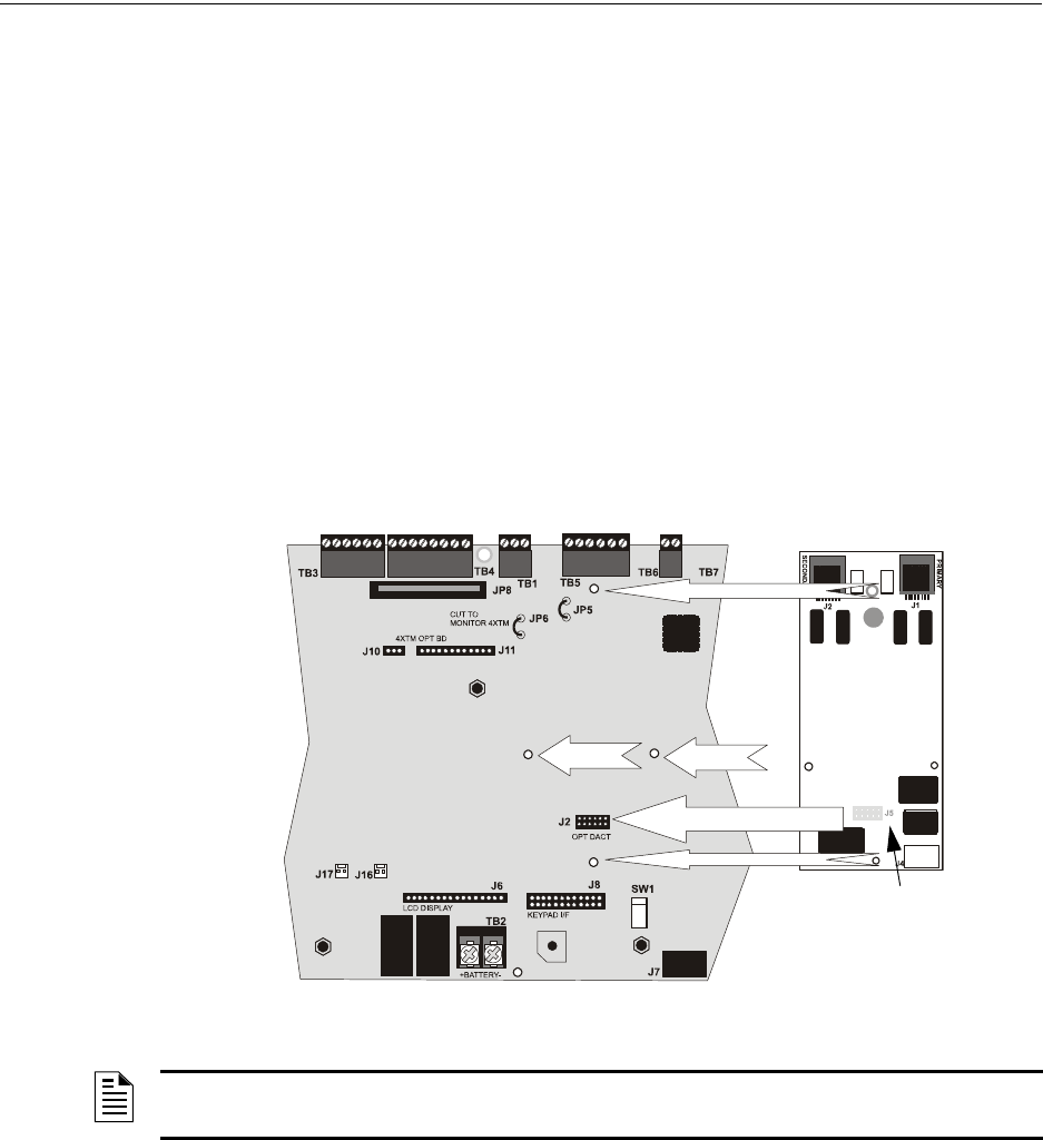
Figure 2.12 DACT-UD2 J1 Connector to FACP J2 Connector
J5
J2
Standoff 3
Standoff 2
Standoff 1
J1 Connector located on
back of DACT-UD2 module
96dialx2.wmf
NOTE: It is important that the supplied hardware be used to secure the module in order to help
protect against electrical transients.