


164 MS-9600LS Series Manual — P/N 52646:B2 2/12/2010
Operating Instructions Read Status
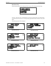
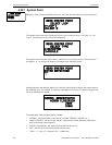
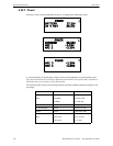
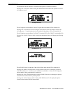
4.22.3 Power
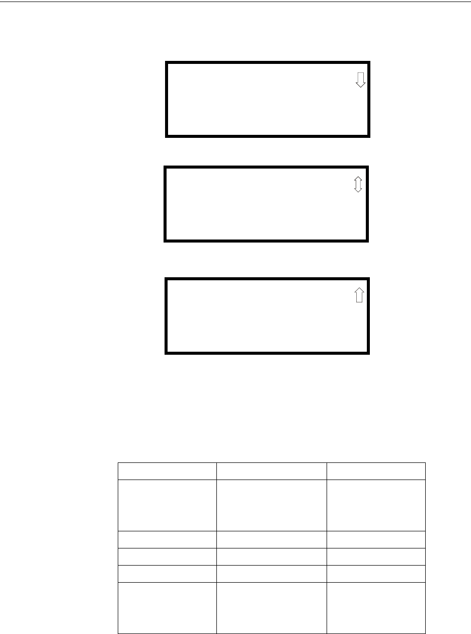
Pressing 3 while viewing Read Status Screen #1 will display the following screens:
A real-time display of control panel voltages can be used to determine if system problems exist.
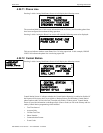
Note that Zones Screen #3 will only be displayed if the NACKEY NAC option card is installed, in
JP8 of the main circuit board, for Class B operation.
The following table lists the circuit being measured, possible conditions and their respective volt-
age ranges:
Circuit Condition Voltage Range
Battery
Normal Battery (nominal) 27.05 to 28.15 VDC
Low Battery 20.0 to 20.8 VDC
No Battery 0 to 18.36 VDC
24V Resettable Normal 21.25 to 27.50 VDC
24V Nonresettable Normal 21.25 to 27.50 VDC
Charger Normal 27.05 to 28.15 VDC
NACs
Normal -1.3 to -1.6 VDC
Open Circuit -2.3 to -2.5 VDC
Short Circuit 0 to 1.0 VDC
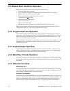
POWER
BATTERY 27.21V
24 V RST 25.31V
Zones Screen #1
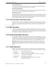
POWER
CHARGER 28.36V
NAC 1 -2.39V
NAC 2 -2.39V
Zones Screen #2
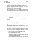
POWER
NAC 3 -2.39V
NAC 4 -2.39V
Zones Screen #3