


176 MS-9600LS Series Manual — P/N 52646:B2 2/12/2010
Power Supply Calculations Calculating the System Current Draw
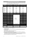
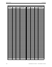
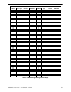
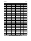
Table 5.3 contains columns for calculating current draws. For each column, calculate the current
and enter the total (in amperes) in the bottom row. When finished, copy the totals from Calculation
Column 2 and Calculation Column 3 to Table 5.4 on page 177.
Calculation Column 1
Primary, Non-Fire Alarm Current (amps)
Calculation Column 2
Primary, Fire Alarm Current (amps)
Calculation Column 3
Secondary, Non-Fire Alarm Current (amps)
Device Type Qty X[current draw]= Total Qty X [current draw] = Total Qty X[current draw]= Total
Main Circuit Board 1 X[0.160]= 0.160 1 X[0.253]= 0.253 1 X[0.103]= 0.103
ANN-80 [ ] X[0.037]= [ ] X[0.040]= [ ] X[0.015]=
ANN-(R)LED [ ] X[0.028]= [ ] X[0.068]= [ ] X[0.028]=
ANN-RLY [ ] X[0.015]= [ ] X[0.075]= [ ] X[0.015]=
ANN-I/O [ ] X[0.035]= [ ] X[0.200]= [ ] X[0.035]=
ANN-S/PG [ ] X[0.045]= [ ] X[0.045]= [ ] X[0.045]=
ACM-8RF [ ] X[0.030]= [ ] X[0.158]
1
= [ ] X[0.030]=
ACM-16ATF
ACM-32AF
[ ] X[0.040] [ ] X[0.056]
2
= [ ] X[0.040]=
AEM-16ATF
AEM-32AF
[ ] X[0.002] [ ] X[0.018]
2
= [ ] X[0.002]=
AFM-16ATF
AFM-32AF
[ ] X[0.040] [ ] X[0.056]
2
= [ ] X[0.040]=
AFM-16AF [ ] X[0.025] [ ] X[0.065]
2
= [ ] X[0.025]=
DACT-UD2 [ ] X[0.020] [ ] X[0.029]= [ ] X[0.017]=
LDM-32F [ ] X[0.040] [ ] X[0.056]
3
= [ ] X[0.040]=
LDM-E32F [ ] X[0.002] [ ] X[0.018]= [ ] X[0.002]=
LCD-80F & LCD-80FC [ ] X[0.064] [ ] X[0.064]= [ ] X[0.025]=
4XTMF [ ] X[0.005]= [ ] X[0.011]
4
= [ ] X[0.005]=
4-wire Detector Heads [ ] X[ ]
5
= [ ] X[ ]= [ ] X[ ]=
Power Supervision Relays
6
[ ] X[0.025]= [ ] X[0.025]= [ ] X[0.025]=
SLC-2LS Expander [ ] X[0.02500]= X[0.02600]= [ ] X[0.01900]=
CP350 & CP355 [ ] X[0.00030]=
maximum alarm draw
for all devices:
with one (1) SLC Loop
with two (2) SLC Loops
0.400
0.800
[ ] X[0.00030]=
SD350 & SD355 [ ] X[0.00030]= [ ] X[0.00030]=
SD350T & SD355T [ ] X[0.00030]= [ ] X[0.00030]=
AD350 & AD355 [ ] X[0.00030]= [ ] X[0.00030]=
H350 & H355 [ ] X[0.00030]= [ ] X[0.00030]=
H350R & H355R [ ] X[0.00030]= [ ] X[0.00030]=
H355HT [ ] X[0.00030]= [ ] X[0.00030]=
D350P & D350PL [ ] X[0.00030]= [ ] X[0.00030]=
D350RP & D350RPL [ ] X[0.00030]= [ ] X[0.00030]=
B501BH & B501BHT
7
[ ] X[0.001]= [ ] X[0.001]=
B224RB Relay Base [ ] X[0.00050]= [ ] X[0.00050]=
B224BI Isolator Base [ ] X[0.00045]= [ ] X[0.00045]=
MMF-300 [ ] X[0.00040]= [ ] X[0.00040]=
MMF-300-10 [ ] X[0.00350]= [ ] X[0.00350]=
MDF-300 [ ] X[0.00075]= [ ] X[0.00075]=
MMF-301 [ ] X[0.000375]= [ ] X[0.000375]=
MMF-302 [ ] X[0.00027]= [ ] X[0.00027]=
MMF-302-6 [ ] X[0.00200]= [ ] X[0.00200]=
BG-12LX [ ] X[0.00030]= [ ] X[0.00030]=
CMF-300 [ ] X[0.00039]= [ ] X[0.00039]=
CMF-300-6 [ ] X[0.00225]= [ ] X[0.00225]=
CRF-300 [ ] X[0.00027]= [ ] X[0.00027]=
CRF-300-6 [ ] X[0.00145]= [ ] X[0.00145]=
I300 [ ] X[0.00040]= [ ] X[0.00040]=
NAC #1
8
[ ] X[ ]=
NAC #2 [ ] X[ ]=
NAC #3 [ ] X[ ]=
NAC #4 [ ] X[ ]=
Current Draw from TB3
(nonalarm
9
)
[ ]= [ ] [ ]= [ ] [ ]=
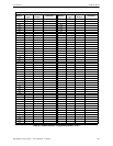
Sum each column
10
for
totals
Primary Non-Alarm = Primary Alarm = Secondary Non-Alarm =
Table 5.3 System Current Draw Calculations
1 All eight ACM-8RF relays activated on a single module.
2 All annunciator LEDs on
3 LDM-32F with LEDs on
4 If using the Reverse Polarity Alarm output, add 0.005 amps; if using the Reverse Polarity Trouble output, add
another 0.005 amps.
5 Refer to the Device Compatibility Document for standby current.
6 Must use compatible listed Power Supervision Relay.
7 Maximum alarm current for each sounder base is 0.015 amps which must be supplied by aux. 24VDC source.
8 Current limitation of Terminal TB4 circuits is 3.00 amps per NAC.
9 The total standby current must include both the resettable (TB3 Terminals 1 & 2) and nonresettable (TB3 Terminals
3 & 4, 5 & 6) power. Caution must be taken to ensure that current drawn from these outputs during alarm does not
exceed maximum ratings specified. Current limitations of TB3 circuits is 3.0 amps per output
10 Total current draw listed above cannot exceed 7.0 amps in alarm.