


150 MS-9600LS Series Manual — P/N 52646:B2 2/12/2010
Section 4: Operating Instructions
4.1 Panel Control Buttons
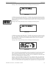
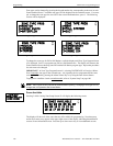
4.1.1 Acknowledge/Step
The first press of the Acknowledge/Step key silences the piezo sounder, changes flashing LEDs to
steady and also changes the status field on the LCD display from capital letters to small letters.
When the piezo is silenced, an acknowledge message is sent to the printer and the history file.
Acknowledge also sends a silence piezo command to the optional annunciators connected to the
FACP.
When more than one event exists, the first press of the Acknowledge/Step key functions as
described in the preceding paragraph. Subsequent pressing of the key steps through each off-nor-
mal active event, with alarm events having a higher priority than trouble and supervisory events.
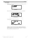
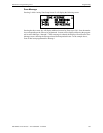
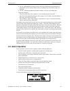
4.1.2 Alarm Silence
The Alarm Silence key performs the same functions as Acknowledge/Step. In addition, if an alarm
exists, it turns off all silenceable NACs (Notification Appliance Circuits) and causes the Alarm
Silenced LED to turn on. It also sends an ‘alarm silenced’ message to the printer, history file and
optional annunciators. A subsequent new alarm will resound the system NACs. Note that the
Alarm Silenced LED is turned off by pressing the Reset key, the Drill key or subsequent activation
of the NACs.
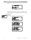
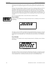
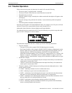
4.1.3 Drill/Hold 2 Sec
When the Drill key is held for a minimum of two seconds (time required to prevent accidental acti-
vations), the FACP turns on all main panel NAC outputs and all silenceable circuits such as control
modules that are programmed as silenceable, and turns off the Alarm Silenced LED if it was previ-
ously on. The EVAC IN SYSTEM message is shown on the LCD display. The same message is sent
to the printer and history file. The Alarm Silence key can be used to turn off all silenceable NAC
outputs following activation by the Drill key.
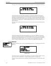
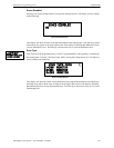
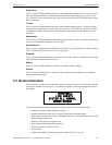
4.1.4 Reset
Pressing and releasing the Reset key turns off all control modules and NACs, temporarily turns off
resettable power to 4-wire detectors, causes a RESET IN SYSTEM message to be displayed on the
LCD and sends the same message to the printer and history file. It also performs a lamp test by
turning on all LEDs (except the Ground LED), piezo sounder and LCD display segments after the
Reset key is released. Any alarm or trouble that exists after a reset will resound the system.
4.2 LED Indicators
The nine LED indicators, which are located on the front panel, operate as follows:
AC Power
This is a green LED which illuminates if AC power is applied to the FACP. A loss of AC power
will turn off this LED
Fire Alarm
This red LED flashes when one or more alarms occur. It illuminates steady when the Acknowl-
edge/Step or Alarm Silence key is pressed. The Fire Alarm LED turns off when the Reset key is
pressed. The LED will remain off if all alarms have been cleared.