


56 MS-9600LS Series Manual — P/N 52646:B2 2/12/2010
Installation Optional Modules and Devices
Remote Station Service (NFPA 72 Remote Station Fire Alarm Systems) - Intended for connec-
tion to a polarity reversal circuit or a Remote Station receiving unit having compatible rat-
ings:
Maximum load for each circuit: 10 mA
Reverse polarity output voltage: 24 VDC
Remote Alarm and Remote Trouble wiring can leave the building
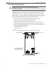
Before installing the module, place the disconnect switch to the right (disconnect) position to pre-
vent accidental activation of the municipal box. Note that a Disconnect LED will illuminate after
the module is installed in the FACP. In addition, the System Trouble LED will turn on to indicate
the Disconnect condition.
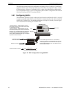
The following steps must be followed when installing the 4XTMF module:
1. Remove all power (AC and DC) from the FACP before installing 4XTMF
2. Cut jumper JP6 on the main circuit board to allow the control panel to supervise the 4XTMF
module
3. The NACKEY Card must be separated at the score mark to allow connection of the 4XTMF
module (refer to Figure 2.6 on page 48 for complete information)
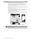
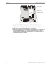
4. Carefully plug the connectors on the 4XTMF module into connectors J10 and J11 on the FACP
main circuit board, being careful not to bend any pins
5. Secure 4XTMF module to standoffs with supplied screws.
6. Reapply power to the FACP
7. For proper 4XTMF operation, the output relays must be programmed for the factory default
settings as shown on the PC board silkscreen: Alarm Relay, Trouble Relay and Supervisory
Relay
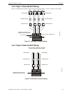
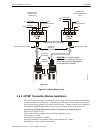
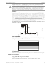
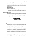
Figure 2.15 4XTMF Transmitter Module
Connect to FACP J10 & J11
Disconnect Switch
shown in disconnect
position
TBL Jumper
Remote Alarm (power-limited)*
Remote Trouble (power-limited)*
No connection
Municipal Box (nonpower-limited)*
1 2 3 4 5 6 7
+ - + - + -
Polarities are shown for module activation
Note: 4XTMF Module is not suitable for transmitting reverse
polarity supervisory signal.
* Wiring from these terminals
can exit the protected
premises. Dummy load
terminals 6 and 7 (4.7K, ¼
watt resistor) if Municipal Box
is not connected.
Disconnect LED
4xtmfl.wmf