


MS-9600LS Series Manual — P/N 52646:B2 2/12/2010 27
Accessories Product Description
ANN-80 Remote Fire Annunciator
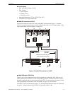
The ANN-80(-W) Annunciator is a compact, 80 character, backlit LCD remote fire annunciator. It
mimics the display on the control panel and will annunciate device type, point alarm, trouble or
supervisory condition, zone assignment plus any custom alpha labels programmed into the FACP.
The annunciator also provides system status LEDs to display AC Power, Alarm, Trouble, Supervi-
sory and Alarm Silenced conditions. Additionally, the annunciator is capable of remotely perform-
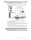
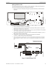
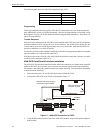
ing critical system functions such as Acknowledge, Silence, Reset and Drill. Communication
between the ANN-80 and FACP is accomplished over a two wire RS-485 serial interface employ-
ing the ANN-BUS communication format. The devices are powered, via two additional wires,
from either the host FACP or remote UL-listed, filtered, power supply.
The function buttons, keyswitch and piezo sounder may be individually enabled and disabled
through the FACP software. Refer to “ANN-BUS Options” on page 121 for a description of this
feature and programming information.
Note that if the keyswitch is enabled and remains in the unlocked position for more than two min-
utes without any buttons being pressed on the annunciator, a trouble indication will be annunciated.
Specifications
• Operating Voltage Range: 18 VDC to 28 VDC
• Current Consumption @ 24 VDC nominal (filtered and nonresettable):
• Normal/Standby (no activity): 37.0 mA
• Trouble: 39.0 mA
• Alarm: 40.0 mA
• AC Fail ( not backlit): 15.0 mA
• For use indoors in a dry location
Installation
Ensure that all power (AC and DC) has been removed from the FACP before installing the annunci-
ator.
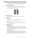
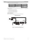
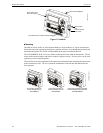
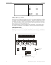
Opening/Closing Annunciator
The following procedure details the steps used to open the annunciator in order to access the termi-
nal block and DIP switches (refer to Figure 1.5 on page 28):
1. Turn the key switch to the ON (Unlocked) position by turning the key counter-clockwise.
2. Push in the snap latch located on the right side of the unit while pulling the cover open.
3. To close the cover, make certain the key switch is in the ON (Unlocked) position. Swing the
cover closed, snapping it shut.
4. Turn the key switch to the OFF (Locked) position by turning clockwise and remove the key.
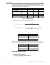
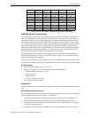
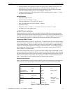
Address
Switch 5
1
1 Switch 5 must be set to OFF for ANN-BUS devices to be recognized.
Switch 4 Switch 3 Switch 2 Switch 1
not valid OFF OFF OFF OFF OFF
01 OFF OFF OFF OFF ON
02 OFF OFF OFF ON OFF
03 OFF OFF OFF ON ON
04 OFF OFF ON OFF OFF
05 OFF OFF ON OFF ON
06 OFF OFF ON ON OFF
07 OFF OFF ON ON ON
08 OFF ON OFF OFF OFF