


Honeywell
MK VI MK VIII EGPWS Installation Design Guide
Proprietary notice on title page applies
CAGE CODE: 97896 SCALE: NONE SIZE: A DWG NO: 060-4314-150 REV:
SHEET
49
3.8.2 Terrain Display Configuration Group ..................................................................................................................70
3.8.3 Display Input Control Group ................................................................................................................................70
3.8.4 Output 429 Bus Group ..........................................................................................................................................71
3.8.5 Instructions............................................................................................................................................................71
3.8.6 Sample Display Schematics...................................................................................................................................71
3.9 C
ATEGORY 7 – OPTIONS SELECT GROUP #1 ................................................................................................................. 88
3.9.1 Steep Approach .....................................................................................................................................................88
3.9.2 TA&D Alternate Pop-up........................................................................................................................................88
3.9.3 Peaks Mode ...........................................................................................................................................................88
3.9.4 Obstacle Awareness ..............................................................................................................................................88
3.9.5 Bank Angle Callout Enabling................................................................................................................................89
3.9.6 Flap Reversal ........................................................................................................................................................89
3.9.7 GPS Altitude Reference.........................................................................................................................................89
3.9.8 Instructions............................................................................................................................................................90
3.10 C
ATEGORY 8 – RADIO ALTITUDE INPUT SELECT ........................................................................................................ 91
3.10.1 Radio Altitude Input ............................................................................................................................................91
3.10.2 Decision Height Discrete Input...........................................................................................................................91
3.10.3 Digital Radio Altitude Interface (Cat. 8 ID 2).....................................................................................................91
3.10.4 Analog Radio Altitude Interface (Cat. 8 ID 0,1,3,4)............................................................................................92
3.10.5 Digital – ARINC 429 Dual IOC Buses (Cat. 8 ID 251- 255) ..............................................................................92
3.10.6 Instructions..........................................................................................................................................................93
3.11 C
ATEGORY 9 – NAVIGATION INPUTS SELECT ............................................................................................................. 94
3.11.1 Navigation Inputs Select (Glideslope & Localizer Inputs)..................................................................................94
3.11.2 Glideslope Validity..............................................................................................................................................94
3.11.3 Localizer Validity ................................................................................................................................................94
3.11.4 ILS Tuned Discrete Input #1 (+28V) and #2 (GND)...........................................................................................94
3.11.5 Analog Glideslope Interface (Cat. 9 ID 0,1,5) ....................................................................................................95
3.11.6 Digital Glideslope / Localizer / ILS Select Interface (Cat. 9 ID 2,3,4) ...............................................................96
3.11.7 Digital – ARINC 429 Dual IOC buses (Cat. 9 ID 250 - 255)..............................................................................96
3.11.8 Instructions..........................................................................................................................................................97
3.12 C
ATEGORY 10 – ATTITUDE INPUT SELECT.................................................................................................................. 98
3.12.1 Roll Angle............................................................................................................................................................98
3.12.2 Analog Pitch & Roll Angle (Synchro) (Cat. 10 ID 0,2,4)....................................................................................98
3.12.3 Digital Pitch & Roll Angle (ARINC 429 High Speed) (Cat. 10 ID 5 & 6) ..........................................................99
3.12.4 Digital – ARINC 429 Dual IOC buses (Cat. 10 ID 253 & 255)..........................................................................99
3.12.5 Instructions..........................................................................................................................................................99
3.13 C
ATEGORY 11 – HEADING INPUT SELECT................................................................................................................. 100
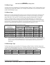
3.13.1 Magnetic Heading.............................................................................................................................................100
3.13.2 Analog Heading (Synchro) (Cat. 11 ID 0).........................................................................................................100
3.13.3 Digital – ARINC 429 AHRS Input (Cat. 11 ID 2 & 3).......................................................................................101
3.13.4 Digital – ARINC 429 Dual IOC buses (Cat. 11 ID 254 & 255)........................................................................101
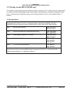
3.13.5 Instructions........................................................................................................................................................101
3.14 C
ATEGORY 12 – WINDSHEAR INPUT SELECT ............................................................................................................ 102
3.14.1 No Windshear....................................................................................................................................................102