


Honeywell
MK VI MK VIII EGPWS Installation Design Guide
Proprietary notice on title page applies
CAGE CODE: 97896 SCALE: NONE SIZE: A DWG NO: 060-4314-150 REV:
SHEET 224
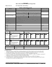
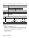
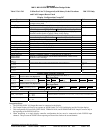
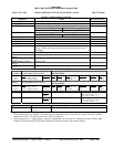
Table 5.3.6.1-241 Collins Pro Line 21 (Integrated) with binary Peaks Elevations
and Full Compass Raster Patch
MK VIII Only
Display Configuration Group 247
Function Value Reference section
Display Type Collins ProLine 21 Integrated, with binary peaks elevations and full
compass raster patch
Sweep Type Fan Mode with +/- 90 degree limit
Category 7, Options Select Group #1
TA&D Alternate Pop Up: False TA&D Alternate Pop Up: True
Auto Pop Up
Category 7 does not affect pop up logic. The display controls pop up,
therefore enable/disable of pop up is done via the display.
5.3.7
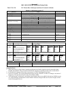
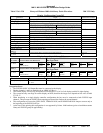
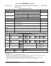
Category 7, Options Select Group #1
Peaks Enable: False Peaks Enable: True
Peaks Mode
Peaks Off Peaks On
5.3.7
Binary Peaks Elevations Yes - Data passed by ARINC 429, Labels 011 and 012
Manual Select Selection is controlled by display
Manual Deselect Deselection is controlled by display
Auto Range Yes (10 NM) controlled by display
Moving Marker No
Overlay Page No
Display bus type ARINC Compatible Format – Collins ProLine 21 (label 077)
Terrain Mode
Annunciation
ProLine 21 system outputs Terrain Mode annunciation, it does not use
EGPWS ASCII message.
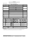
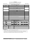
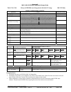
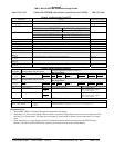
DISPLAY BUS #1
453TX_1
CONNECT TO:
A = J1-58
B = J1-59
Terrain Display data to Primary Flight Display/Multi Function display #1 4.2.13.2
7.2
DISPLAY BUS #2
453TX_2
CONNECT TO:
A = J1-56
B = J1-57
Terrain Display data to Primary Flight Display/Multi Function display #2 4.2.13.2
7.2
Display Input Control Group 254
CHANNEL
429RX_1
CONNECT TO: IOC #1 Bus
Format: ARINC 429 (High Speed)
Fault Designation: IOC BUS 1
Bus Type: Basic
A = J2-37
B = J2-36
Data
Range (Mode/Range Word)
Reference
6.2.21
Label
176
Sig. Bits
Discrete
Range
5-640NM
Signal Type
Basic
Resolution
N/A
Rate (ms)
50
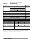
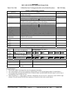
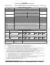
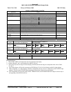
CHANNEL
429RX_3
CONNECT TO: IOC #2 Bus
Format: ARINC 429 (High Speed)
Fault Designation: IOC BUS 2
Bus Type: Basic
A = J2-41
B = J2-40
Data
Range (Mode/Range Word)
Reference
6.2.21
Label
176
Sig. Bits
Discrete
Range
5-640NM
Signal Type
Basic
Resolution
N/A
Rate (ms)
50
Output 429 Bus Group 1
Channel Pins Comments
429TX_1 (Low Speed) A = J2-43
B = J2-42
Transmits (Section 7) Label sets: 7.1.1.x, 7.1.2.x, 7.1.3.x, 7.1.4.x, 7.1.5.x and 7.1.6.x
429TX_2 (Low Speed) A = J2-26
B = J2-9
Transmits (Section 7) Label sets: 7.1.1.x, 7.1.2.x, 7.1.3.x, 7.1.4.x, 7.1.5.x and 7.1.6.x
Integration Notes:
1. The EGPWS ARINC 429 Output Bus must be connected to the display.
2. The Terrain Display will Pop-Up in response to EGPWS label 274, bit 28 (left display) and bit 29 (right display).
3. This configuration will cause the GPWS INOP, TERRAIN INOP, and WINDSHEAR INOP lamps to turn on only at
the beginning of the EGPWS Self Test.
4. When interfacing to a single display controller configuration the bus must be connected to both EGPWS input
channels. This prevents the EGPWS from reporting an external bus fault on the second channel.