


IPGSM-DPC Commercial Fire Communicator – Installation and Setup Guide
– 7 –
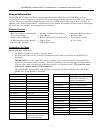
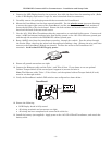
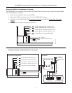
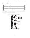
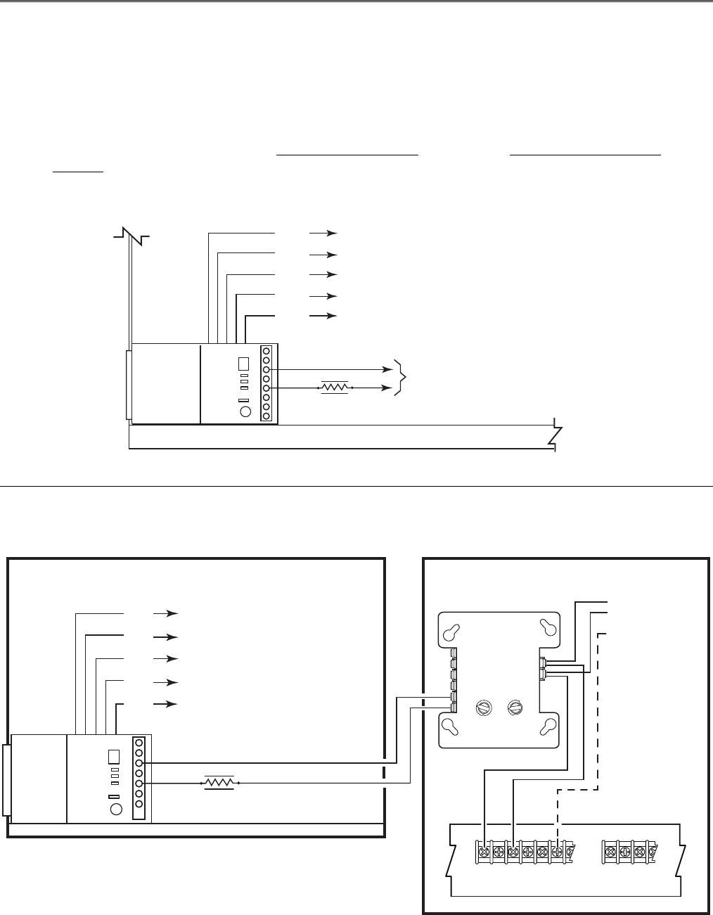
Wiring the 659EN Line Fault Monitor (if required)
The IPGSM-DPC is compatible with the Honeywell brand FACP’s listed on page 1 when the model 659EN
Line Fault Monitor is installed.
1. Refer to the installation guide for the 659EN.
2. Mount the 659EN on the lower left side of the IPGSM-DPC cabinet.
3. DO NOT cut the 659EN’s BLACK Output Relay Jumper
or the BLUE Voltage Trip Threshold
Jumper.
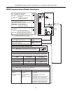
4. Complete the interface wiring as shown below:
to Dialer Capture Module, Terminal, Tip 2
to Dialer Capture Module, Terminal, Ring 2
to Power Boost 1, Terminal, OUTPUT 1, DC+
to Power Boost 1, Terminal, OUTPUT 1, DC-
to Power Boost 1, Terminal, ERTH GND
Wire to a
Zone on the Fire Panel
659EN
YEL
ORG
RED
BLK
GRN
IPGSM-DPC-013-V0
4.7K, 1/2 watt
IPGSM-DPC
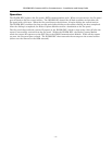
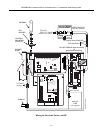
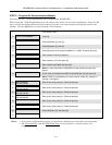
Example wiring for an addressable fire control panel:
T11
T10
T9
T8
T7
T6
T1
T2
T3
T4
T5
1
0
2
3
4
5
6
7
8
9
10
11
12
13
14
15
1
0
2
3
4
5
6
7
8
9
TENS ONES
LOOP ADDRESS
TOP
B+ A+ B- A- A B
NO NC
C
TB2
TB5
SLC Loop
FIRE LITE Addressable Fire Alarm Control Panel
MS-9050UD
MMF-300A
Monitor Module
- To next device
+ on SLC Loop
Braided-shield/Drain
Wire
RELAY 1
ALARM CONTACTS
IPGSM-DPC
Commercial Fire Communicator
to Dialer Capture Module, Terminal, Tip 2
to Dialer Capture Module, Terminal, Ring 2
to Power Boost 1, Terminal, OUTPUT 1, DC+
to Power Boost 1, Terminal, OUTPUT 1, DC-
to Power Boost 1, Terminal, ERTH GND
659EN
YEL
ORG
RED
BLK
GRN
4.7K, 1/2 watt
B+ B- Shield
IPGSM-DPC-014-V0