


IPGSM-DPC Commercial Fire Communicator – Installation and Setup Guide
– 4 –
STEP 3 – Determine the Signal Strength and Select a Location
IMPORTANT - Do Not mount this device outdoors.
RF Exposure
Warning – The antenna(s) used for this transmitter must be installed to provide a separation
distance of at least 20 cm from all persons and must not be collocated or operating in con-
junction with any other antenna or transmitter.
When choosing a suitable mounting location, understand that signal strength is very important for proper
operation. For most installations using the supplied antenna, mounting the unit as high as practical, and
avoiding large metal components provides adequate signal strength for proper operation.
In this procedure, you will use the iGSM Communications Module to determine signal strength in order to
find a suitable mounting location.
Note: Since the SIM is already activated, the RSSI signal strength indicators will indicate
signal strength.
1. You will need a fully charged 12V battery.
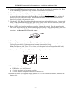
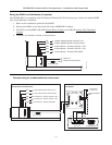
2. Attach the Antenna (see illustration on page 6).
3. Temporarily wire the battery's negative [–] terminal to TB1–4 on the iGSM communications module,
then wire the battery's plus [+] terminal to TB1–2 on the communications module. Wait about one
minute for the module to initialize.
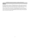
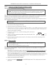
4. Position the assembly near a suitable mounting position and observe
the RSSI display.
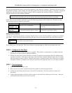
5. Look for a mounting position that yields at least 3 bars lit solid. Four
or five bars are better.
6. Verify the signal strength remains steady for a few minutes, then mark that mounting position.
Disconnect the battery.
STEP 4 – Mount and Wire
For ULC compliant installations, refer to the topic on ULC Compliance in this manual.
For Dry/Indoor use only.
External cabinet wiring MUST be routed in conduit.
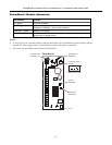
This communicator comes partially assembled with all the components mounted except the Antenna, LED
Display board, and PowerBoost1. To protect certain components on the PowerBoost1, it is shipped un-
mounted but fully wired.
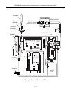
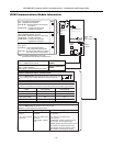
Note: Refer to the diagram on page 6, and to the Wiring Diagram on the inside of the back cover
of
this manual for wiring and component identification.
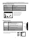
1. Remove knockouts from cabinet to accommodate the power input wires, and wiring to the control
panel. (DO NOT REMOVE the two knockouts directly above the PowerBoost1 module.) Then mount
the cabinet securely to the wall using 4 screws or bolts. Use mounting screws or bolts that are
suitable for the material being anchored to.
2. Ensure the cabinet door lock is installed.
3. Install the two plastic mounting rails
for the LED Display board. They simply snap into the back
plate holes.
3 BARS MIN.
GYGGRY
7845i-GSM-025-V0