


IPGSM-DPC Commercial Fire Communicator – Installation and Setup Guide
– 14 –
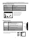
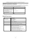
IPGSM-DPC Trouble Detection Information
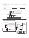
Telco 1 is used for the Fire Panel to output contact ID messages to the IPGSM-DPC, and Telco 2 is used by
the IPGSM-DPC to report faults to the Fire Panel. If Telco 1 is not operational, the Fire Panel will use Telco
2 to report events if there are no faults in the iGSM Communications module.
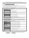
Fault Condition Indication to Fire Panel
PowerBoost1 fault Telco 2 is cut.
iGSM Communications Module fault
Failure of the communications path when
IP only or GSM only is programmed as a
communications path.
Telco 2 is cut.
Failure of both communications paths
when IP&GSM is programmed as a
communications path.
Telco 1 and 2 are cut.
Dialer Capture Module buffer is full.
Hang up. (Panel will retry, giving the buffer a chance to
empty.)
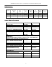
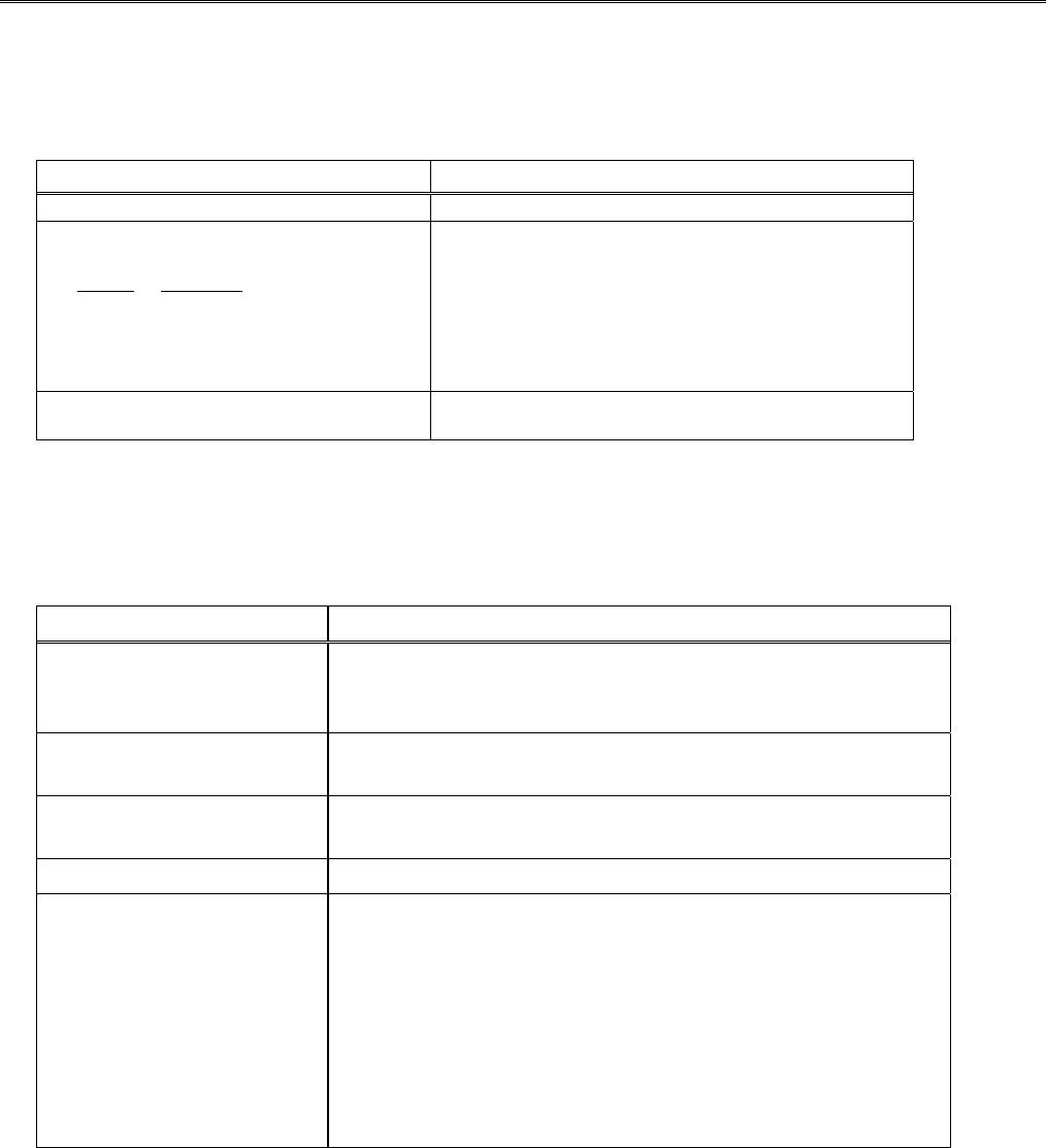
IPGSM-DPC Specifications
ITEM SPECIFICATION
Cabinet Dimensions:
Width = 12 3/4 inches
Height = 14 7/8 inches
Depth = 3 inches
Transformer: 1451-UL9
Primary – 120VAC, 60Hz, 850mA
Secondary – 18VAC, 72VA
Battery:
12V, 7Ah sealed lead acid type (not supplied)
Use a Honeywell 712BNP, Yuasa NP7-12 or equivalent.
Battery Charging Current:
maximum 1A
Supervision:
The Radio (communicator), battery, and AC power, conditions are
monitored by the cabinet indicator LEDs:
RADIO TROUBLE lights when any of these conditions exist.
Both IP and GSM communication paths are lost.
Communicator radio is not registered.
Old Alarm Time has been exceeded. (Message has not been
delivered within the fixed 10 minute window.)
LOW BATTERY lights when the battery voltage is less than 11.5VDC.
AC LOSS lights when the AC power is less than 90VAC.