


IPGSM-DP Commercial Fire Communicator – Installation and Setup Guide
– 1 –
General Information
The IPGSM-DP Commercial Fire Communicator (henceforth referred to as IPGSM-DP) includes everything
you need to upgrade a commercial fire system that previously reported by POTS to a system that uses the
Internet as its primary reporting path, and uses a GSM cellular reporting path as a backup. In addition,
this communicator utilizes a sophisticated power module (PowerBoost1) that monitors and reports AC power
loss, low battery, and missing battery conditions.
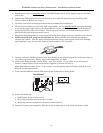
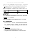
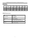
Package Contents
Red Fire Cabinet and Back Plate Antenna and Mounting Adapter LED Display board
Cam Lock with Key PowerBoost1 Mounting Rails (for above)
Dialer Capture Module Battery harness Hardware Bag
iGSM Communications Module Wall Outlet Box (P/N K14358) Transformer, 18VAC (N8167)
50 ohm cable assembly Ferrite Filter
Compatible Fire Panels
The IPGSM-DP works with Fire Panels that use the Contact ID communication format as described in the
SIA DC-05 Standard. After completing the field installation, verify communications with the central station
is successful by sending several events. Also, get confirmation that these events were received.
Note: For a fire panel that has more than 9 active partitions, the first 9 partitions are reported to the
central station uniquely. Beyond 9 partitions, only the 2nd digit of the partition is reported along with
a leading zero (example partition 14 is reported as 04). The installer must inform the central
station of this condition.
Operation
The IPGSM-DP replaces the fire panel's POTS communications path. When an event occurs, the fire panel
goes off-hook to dial the central station. The IPGSM-DP detects the off-hook condition and provides the fire
panel with a dial tone. When the fire panel detects the dial tone, it begins dialing the central station. The
IPGSM-DP considers the three second period after dialing as the number dialing has been completed. After
the dialing is completed, the Dialer Capture Module returns a handshake to the fire panel.
The fire panel then sends the contact ID reports to the IPGSM-DP, which in turn sends a kiss-off after the
report is successfully received from the fire panel. Within the IPGSM-DP, the Dialer Capture Module sends
the contact ID reports over the ECP bus to the iGSM Communications Module. When all the reports are
sent, the fire panel goes on-hook. The IPGSM-DP then transmits the messages to the central station (either
over the internet or the GSM network).
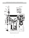
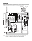
Installation
UL Compliance
To meet UL864/NFPA, ensure the following:
IPGSM-DP must be installed in accordance with NFPA (National Fire Protection Association)
standards 70 and 72.
IPGSM-DP must be mounted in the same room and within 20 feet of the fire panel. The wiring must
be routed through conduit.
IPGSM-DP, and all equipment used for the IP connection (such as the router, hub, modem, etc.) shall
be listed, must be powered from an un-switched branch circuit, and be provided with appropriate
standby power.
IPGSM-DP must use a 7AH battery (not supplied) to provide 24-hour backup capability.